AI technical title is built by Patsnap AI team. It summarizes the technical point description of the patent document.
a technology of ducted lift and vtol aircraft, which is applied in the direction of aircraft, vertical landing/take-off aircraft, rotorcraft, etc., can solve the problems of large aerodynamic drag, relative slow forward speed, and limited forward speed of helicopters less than 200 knots, and achieve high efficiency
Inactive Publication Date: 2016-04-14
JIANG YUN
View PDF18 Cites 14 Cited by
Summary
Abstract
Description
Claims
Application Information
AI Technical Summary
This helps you quickly interpret patents by identifying the three key elements:
Problems solved by technology
Method used
Benefits of technology
Benefits of technology
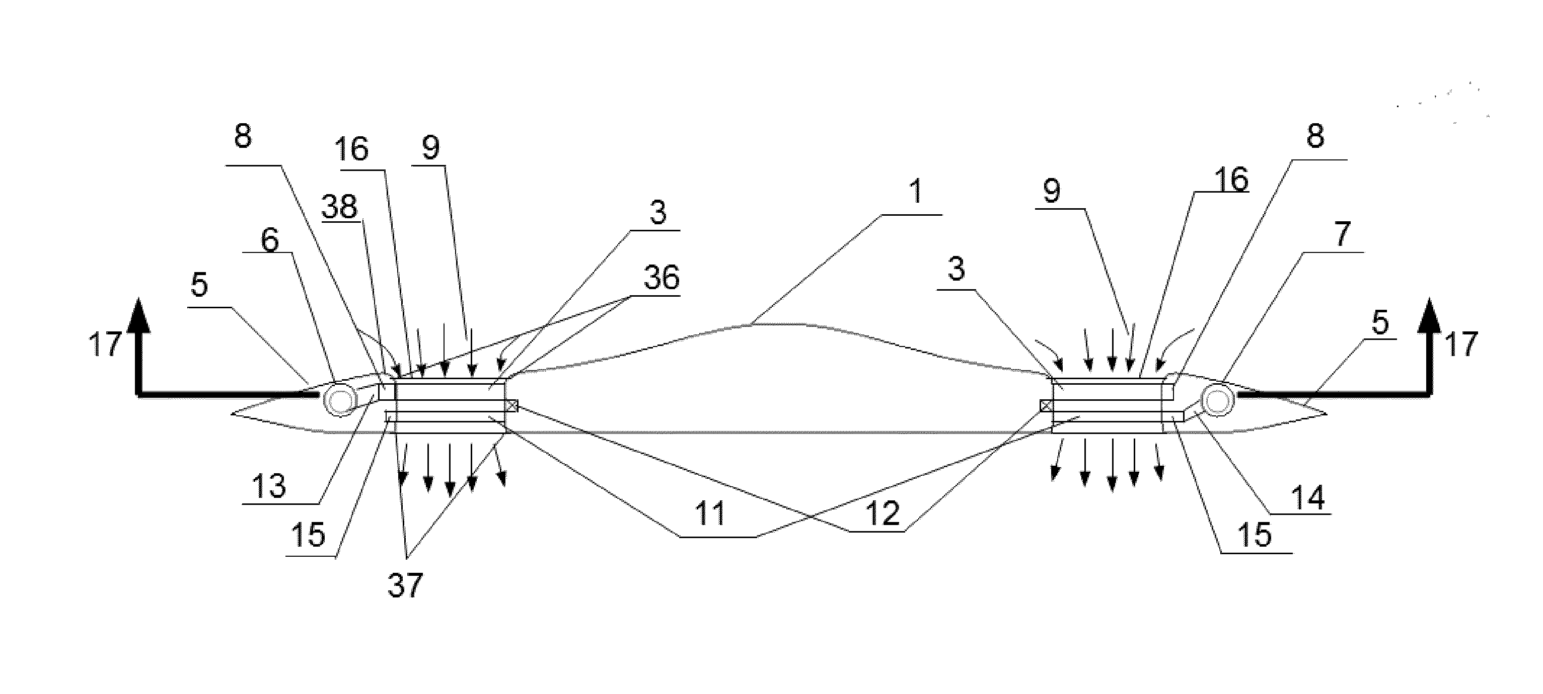
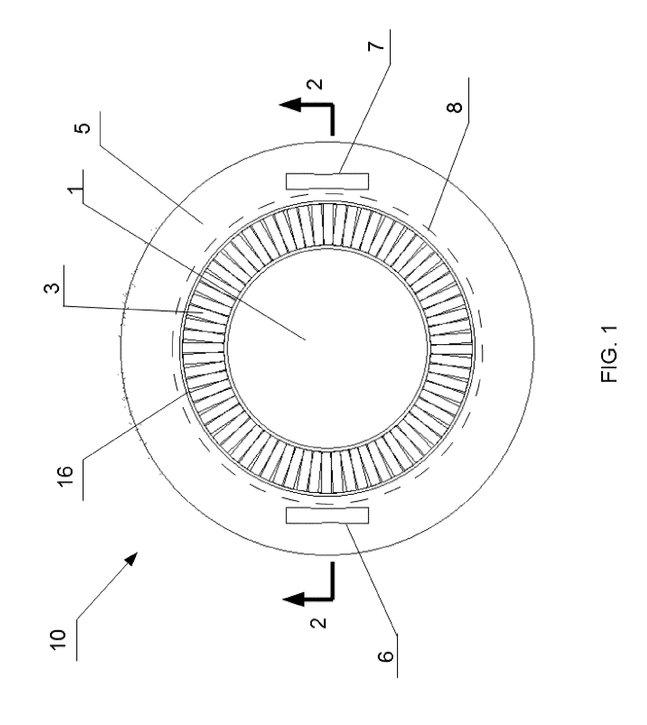
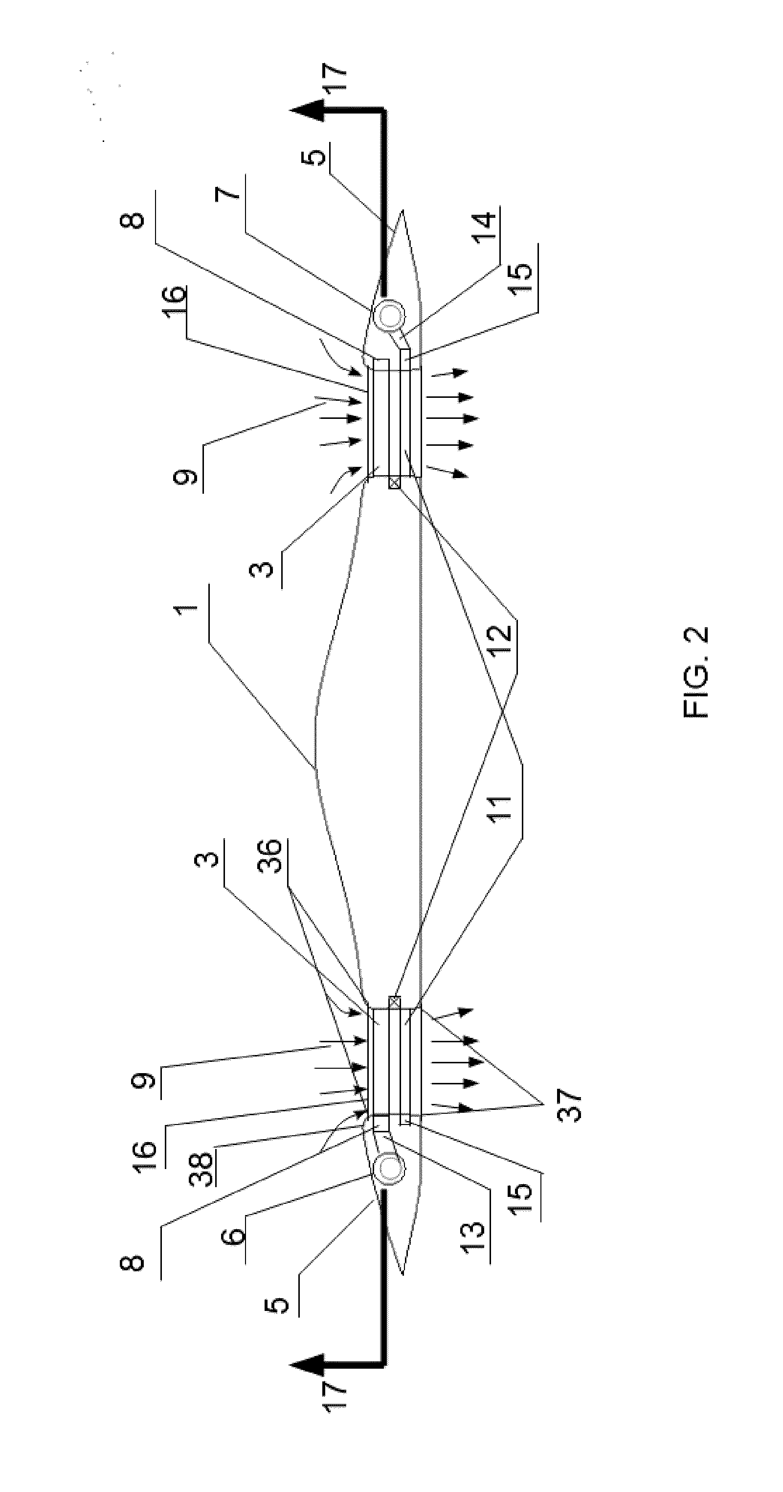
The present invention is a lift system for VTOL aircraft that uses an annular ducted lift fan set mounted between the central fuselage and the peripheral wing. This results in a larger fan area, higher lift efficiency, and lower disc loading compared to traditional helicopters. The system also includes controllable upper shutters and lower louvers to control airflow during transition flight and forward flight, respectively. The curved inlet lips and diffused outlet maximize duct lift and increase lifting efficiency. The larger annular duct does not reduce the duct effect. Overall, the lift system improves the performance of VTOL aircraft.
Problems solved by technology
The primary drawback to conventional fixed wing aircraft is that they must have a runway to create sufficient airflow over the wings such that they may take off and land.
Helicopters have rotary wing capable of vertical flight and hover, but they often have relatively slow forward speeds as the rotating blades create a large aerodynamic drag.
Loss of function of the tail rotor is generally fatal to the airworthiness of the helicopter.
These lead to complex rotor control systems which are difficult and costly to maintain, and which require considerable pilot training and skill.
The large exposed rotor blades are also vulnerable to strikes and dangerous to persons in the vicinity of the aircraft on the ground.
The fan provides significant trust for vertical lift in hover, but its correspondingly large frontal area increases the drag of the aircraft and limits its maximum speed to just barely above supersonic speed.
The nozzles are designed for efficient high speed forward thrust but are very inefficient in vertical lift mode; accordingly much greater power input is required for vertical lift than would otherwise be the case.
The gas usually also have a temperature higher than 800° F., which may cause damage to surfaces such as runways, aircraft carrier decks, and natural terrain.
However, the large propellers limit the top speed to about 300 Knots at sea level due to compressibility effects on the propeller tips.
Another problem with tiltrotors involves stability control difficulties.
The vortex-ring state causes unsteady shifting of the flow along the blade span, and may lead to roughness and loss of aircraft control.
Also, the propellers have a large diameter and may strike the landing surface when the engines are still fully forward.
This design not only limits the size of fans due to the constraint of fuselage and wing size but also increases drag because the wings containing the fans have to be made relatively thick to maintain enough depth of fan ducts.
The thick wings create unacceptable drag during forward flight.
However if the thickness of the wings is made much smaller than the diameter of the fan ducts, the benefits of the duct will be reduced and the vertical thrust produced by the fans will be limited.
According to the momentum theory of ducted fans, high disc loading means higher power required to lift the aircraft, thus leading to low lift efficiency.
However, the space in the conventional aircraft for circular ducted fan is limited.
Like Ryan XV-5A, not only incorporating lift fan in the large relatively thick wings creates unwanted drag during forward flight but also the wing size is not enough to contain larger low disc loading circular fans.
Other designs, such as a huge circular lift fan in the center of the aircraft or a plurality of small circular ducted fans about the aircraft, suffer from other problems, such as difficult layout for fuselage, thick wing, and increased complexity, which make them unpractical so far.
Method used
Image
Click on the blue label to locate the original text in one second.
Reading with bidirectional positioning of images and text.
Examples
Embodiment Construction
[0026]The invention relates to aircraft with annular ducted lift fan system capable of efficient vertical takeoff and landing and horizontal flight. Referring now to the figures, and more particularly to FIG. 1, aircraft according to a first embodiment of the present invention is designated in its entirely by reference number 10. The aircraft 10 has a central fuselage 1, an annular duct 16 in which a lift fan set 3 is mounted, a peripheral wing 5, and two turbofan engines 6, 7. For gas-driven mode, a rectangular-shaped gas chamber 8 is also shown. The annular duct is completely opened with the shutters or aperture and louvers removed. Although the aircraft 10 may have other sizes without departing from the scope of the present invention, in one embodiment the aircraft has a peripheral wing diameter 20 meters, annular duct diameters 10 and 14 meters, fan blade length 2 meters, and depth of duct 1 meter, in order to compare with the rotor diameter 14.64 meters and blade length 7.32 me...
PUM
Abstract
The invention is an annular ducted lift fan system for a VTOL type aircraft. In detail, the invention comprises an annular duct, a lift fan set, engines, a central fuselage, a peripheral wing, and means for pneumatic coupling or mechanic coupling of engines and the lift fan set. The lift fan set is mounted in the annular duct and powered by the engines through pneumatic coupling or mechanic coupling. The annular duct is opened with the lift fan set working to provide high lift efficiency in VTOL mode and transition mode and is closed off to reduce drag in cruise mode.
Description
REFERENCES CITEDU.S. Patent Documents[0001]3,972,490August 1976Zimmermann et al.244 / 12 B4,469,294September 1984Clifton244 / 12.34,474,345October 1984Musgrove244 / 53R4,791,783December 1988Neitzel 60 / 2625,170,963December 1992Beck244 / 12.25,209,428May 1993Bevilaqua et al.244 / 12.35,275,356January 1994Bolinger et al.244 / 12.35,312,069May 1994Bollinger et al.244 / 12.35,320,305June 1994Oatway et al.244 / 12.35,407,150April 1995Sadleir244 / 12.45,507,453April 1996Shapery244 / 12.56,561,456 B1May 2003Devine244 / 12.17,267,300 B2September 2007Heath et al.244 / 12.37,510,140 B2May 2009Lawson et al.244 / 12.57,677,502 B2March 2010Lawson et al.244 / 2078,220,737 B2July 2012Wood et al.244 / 12.38,336,806 B2December 2012Dierksmeier244 / 12.32013 / 0140404June 2013Parks244 / 23ATECHNICAL FIELD[0002]The present invention relates to vertical take-off and landing (VTOL) aircraft and, more specifically, relates to VTOL aircraft wherein annular-ducted lift-fans are used to provide powered lift while in hovering mode and transition...
Claims
Application Information
Patent Timeline
Application Date:The date an application was filed.
Publication Date:The date a patent or application was officially published.
First Publication Date:The earliest publication date of a patent with the same application number.
Issue Date:Publication date of the patent grant document.
PCT Entry Date:The Entry date of PCT National Phase.
Estimated Expiry Date:The statutory expiry date of a patent right according to the Patent Law, and it is the longest term of protection that the patent right can achieve without the termination of the patent right due to other reasons(Term extension factor has been taken into account ).
Invalid Date:Actual expiry date is based on effective date or publication date of legal transaction data of invalid patent.
Patent Type & AuthorityApplications(United States)

