Annular lift fan vtol aircraft

a technology of vertical lift and aircraft, which is applied in the direction of vertical landing/take-off aircraft, jet type power plants, drag reduction, etc., can solve the problems of large aerodynamic drag, relative slow forward speed, and limited forward speed of helicopters less than 200 knots, and achieve high efficiency

Inactive Publication Date: 2018-07-05
JIANG YUN
View PDF1 Cites 1 Cited by
  • Summary
  • Abstract
  • Description
  • Claims
  • Application Information

AI Technical Summary

Benefits of technology

[0013]It is another primary object of the present invention to provide a design for VTOL aircraft having high efficiency in both hover and level flights.

Problems solved by technology

The primary drawback to conventional fixed wing aircraft is that they must have a runway to create sufficient airflow over the wings such that they may take off and land.
Helicopters have rotary wing capable of vertical flight and hover, but they often have relatively slow forward speeds as the rotating blades create a large aerodynamic drag.
A helicopter has a limited forward speed of less than 200 Knots due to compressibility effects on the rotor blade tips when the blades rotate at the speed of sound.
Loss of function of the tail rotor is generally fatal to the airworthiness of the helicopter.
These lead to complex rotor control systems which are difficult and costly to maintain, and which require considerable pilot training and skill.
The large exposed rotor blades are also vulnerable to strikes and dangerous to persons in the vicinity of the aircraft on the ground.
The fan provides significant trust for vertical lift in hover, but its correspondingly large frontal area increases the drag of the aircraft and limits its maximum speed to just barely above supersonic speed.
The nozzles are designed for efficient high speed forward thrust but are very inefficient in vertical lift mode; accordingly much greater power input is required for vertical lift than would otherwise be the case.
The gas usually also have a temperature higher than 800° F., which may cause damage to surfaces such as runways, aircraft carrier decks, and natural terrain.
However, the large propellers limit the top speed to about 300 Knots at sea level due to compressibility effects on the propeller tips.
Another problem with tiltrotors involves stability control difficulties.
The vortex-ring state causes unsteady shifting of the flow along the blade span, and may lead to roughness and loss of aircraft control.
Also, the propellers have a large diameter and may strike the landing surface when the engines are still fully forward.
This design not only limits the size of fans due to the constraint of fuselage and wing size but also increases drag because the wings containing the fans have to be made relatively thick to maintain enough depth of fan ducts.
The thick wings create unacceptable drag during forward flight.
According to the momentum theory of ducted fans, high disc loading means higher power required to lift the aircraft, thus leading to low lift efficiency.
However, the space in conventional aircraft for circular lift fan is limited.
Like Ryan XV-5A, the wing size is not enough to contain larger low disc loading circular fans.
Other designs, such as a huge circular lift fan in the center of the aircraft or a plurality of small circular ducted fans about the central fuselage, suffer from other problems, such as difficult layout for fuselage, thick wing, and increased complexity, which make them unpractical so far.
There have been some disclosures with annular ducted fan in patents, but all these disclosures suffer from various problems.
One problem is that the annular duct is not closed and the fan continues to work in cruise flight.
The horizontal lift fan works efficiently in hover mode but introduces tremendous momentum drag in cruise mode, leading to very low forward speed.
Another problem is to use multi-stage fans or compressor, which cause serious vibration in transition mode due to the strong interaction between the fans and incoming flow.
The last problem is that the duct is not optimized.
The non-optimized duct can greatly reduce the advantages of duct.

Method used


Image

  • Annular lift fan vtol aircraft
  • Annular lift fan vtol aircraft
  • Annular lift fan vtol aircraft

Examples


Embodiment Construction

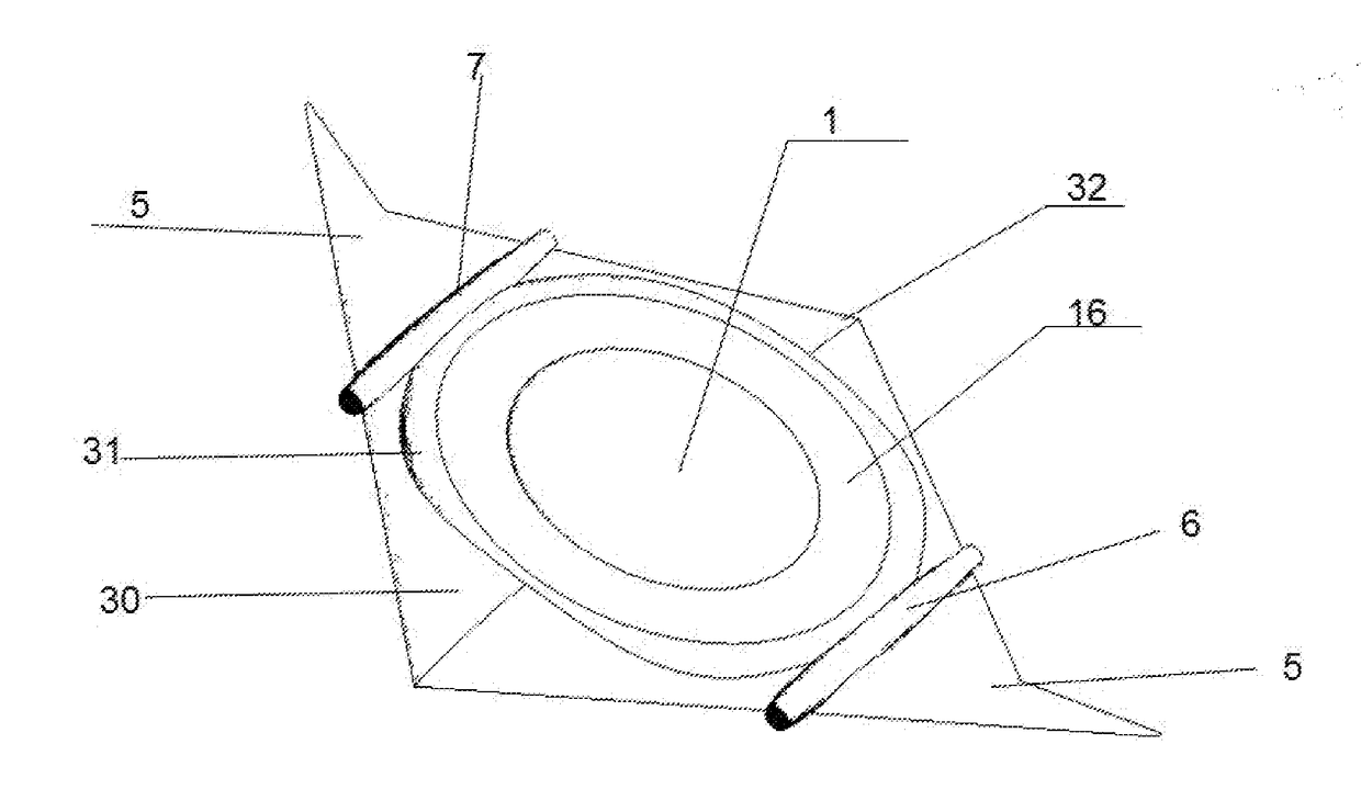
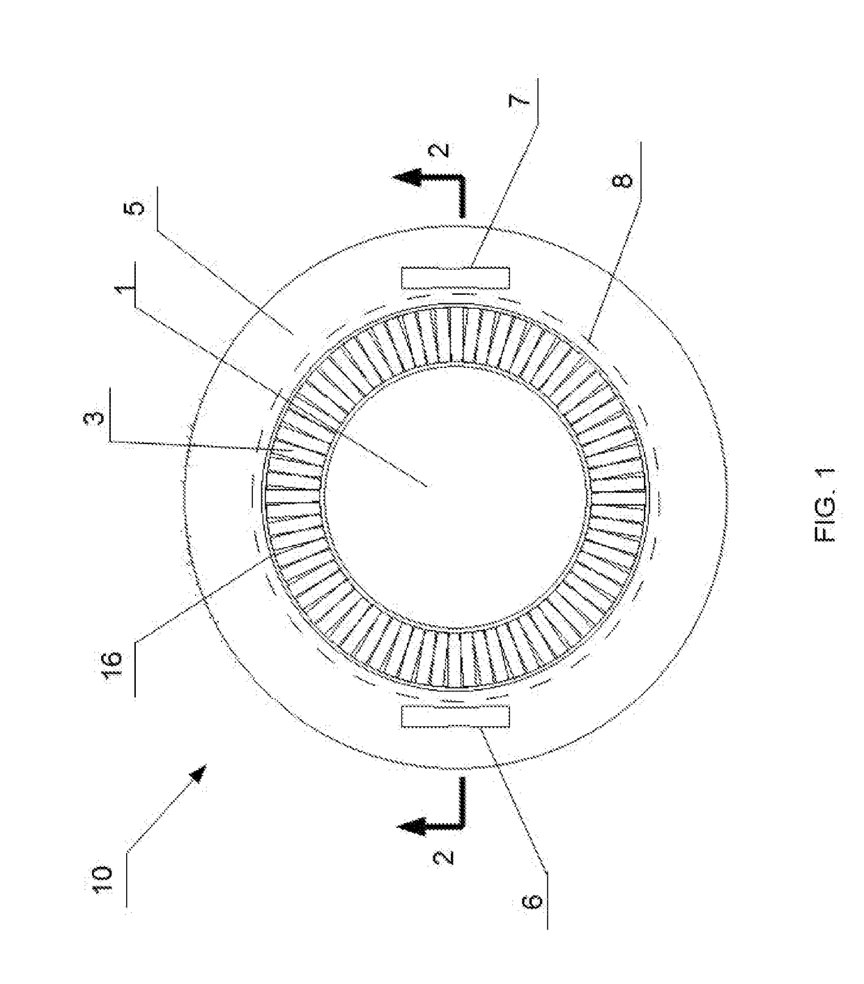
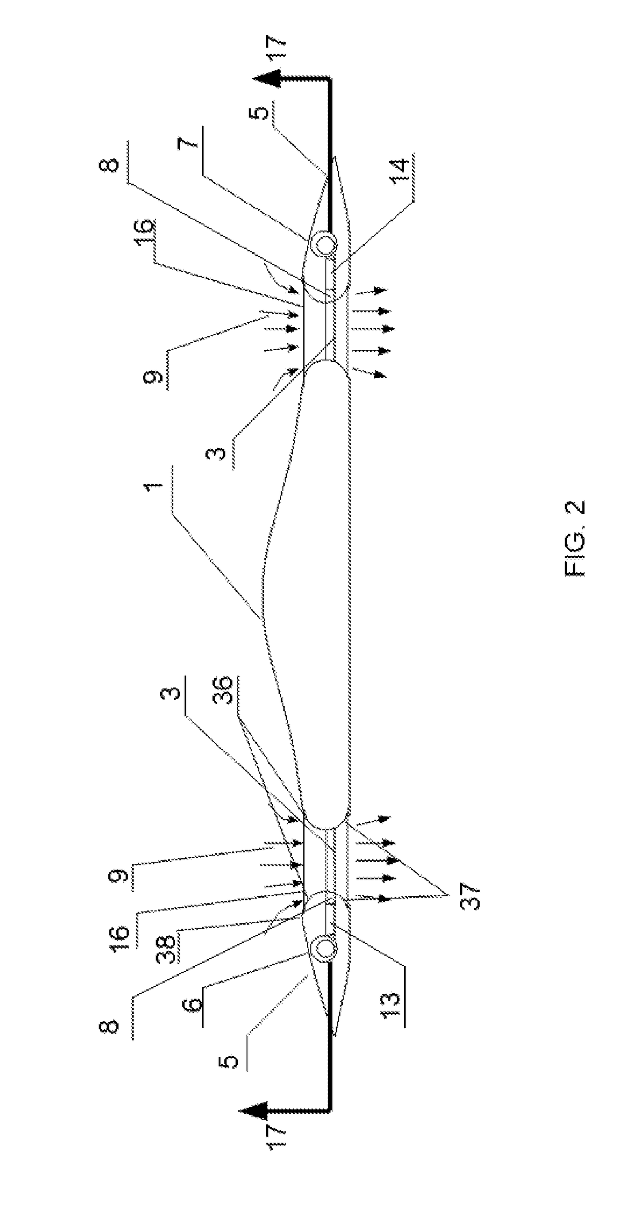
[0023]The invention relates to aircraft with annular lift fan system capable of efficient vertical takeoff and landing and horizontal flight. Referring now to the figures, and more particularly to FIG. 1, aircraft according to a first embodiment of the present invention is designated in its entirety by reference number 10. The aircraft 10 has a central fuselage 1, an annular duct 16 in which a lift fan set 3 is mounted, an outer wing 5, and two turbofan forward engines 6, 7 to propel the aircraft in cruise flight. The forward engines can be one, two or more, and can be any type of engines used in the aerospace industry, such as turbojet engine, turbopropeller engine, turboshaft engine, piston engine, electric motor, without departing from the scope of the present invention. The lift fan set 3 can be pneumatically (gas-driven), mechanically (shaft-driven), or electrically (motor-driven) coupled with the engines 6, 7 in VTOL. For gas-driven mode, a rectangular-shaped gas chamber 8 is ...


PUM


Abstract

The invention is an annular lift fan system for a VTOL type aircraft. In detail, the invention comprises an annular duct (16), a lift fan set (3), engines (6, 7), a central fuselage (1), and an outer wing (5). The lift fan set (3) is mounted in the annular duct (16) and powered by the engines (6, 7) incorporated in the outer wing (5). The annular duct is open for the lift fan set to provide high lift efficiency in VTOL and transition mode, and is closed off by shutters and louvers to provide aerodynamic lift and reduce drag in cruise mode.

Description

TECHNICAL FIELD[0001]The present invention relates to vertical take-off and landing (VTOL) aircraft and, more specifically, relates to VTOL aircraft wherein annular lift fans are used to provide powered lift while in hovering mode and transition mode.BACKGROUND[0002]The primary drawback to conventional fixed wing aircraft is that they must have a runway to create sufficient airflow over the wings such that they may take off and land. Much effort has been directed towards the development of aircraft capable of vertical take-off or landing which are not restricted to airport runways but can land and take-off from any relatively small open area.[0003]There are four types of successful and practical VTOL aircraft so far. They are helicopter, vectored jet aircraft, tiltrotor, and ducted lift-fan aircraft. These aircraft provide solutions to this problem, but also have some disadvantages.[0004]Helicopters have rotary wing capable of vertical flight and hover, but they often have relativel...

Claims


Application Information

Patent Timeline
Patent Type & Authority Applications(United States)
IPC IPC(8): B64C29/00B64C1/16B64C1/00
CPCB64C29/0025B64C1/0009B64C1/16B64C2039/105B64D27/20B64D35/02B64D35/08Y02T50/10
Inventor JIANG, YUN
Owner JIANG YUN
Why Eureka
Try Eureka