System for sealing the secondary flow at the inlet to a nozzle of a turbomachine having a post-combustion chamber

Active Publication Date: 2005-11-22
SN DETUDE & DE CONSTR DE MOTEURS DAVIATION S N E C M A
View PDF13 Cites 14 Cited by
  • Summary
  • Abstract
  • Description
  • Claims
  • Application Information

AI Technical Summary

Benefits of technology

[0008]The object of the invention is to propose a turbomachine as mentioned in the introduction, in which the leaks of secondary air, in particular towards the outside, between the annular channel and the passages of the flaps are eliminated so as to avoid losing engine performance.
[0010]Thus, in operation, the first gasket is held under urging from the pressure of the secondary flux to press slidably against the downstream inside face of the casing and the upstream inside faces of the flaps, thereby preventing leaks of the cold secondary flow to the outside. The positioning of the first gasket naturally depends on the angular positioning of the flaps, and on any possible differences of expansion between the various parts.
[0014]These various dispositions of the gaskets provide good sealing of the gasket walls, together with a desired degree of stiffness.

Problems solved by technology

However, the transmission of this flow between the stationary portions of the post-combustion chamber and the moving portions of the nozzle must be performed in a manner that is as leak tight as possible.
That document does not teach that that type of gasket is capable of providing satisfactory sealing between a stationary annular part and a set of flaps hinged on said part.

Method used


Image

  • System for sealing the secondary flow at the inlet to a nozzle of a turbomachine having a post-combustion chamber
  • System for sealing the secondary flow at the inlet to a nozzle of a turbomachine having a post-combustion chamber
  • System for sealing the secondary flow at the inlet to a nozzle of a turbomachine having a post-combustion chamber

Examples


Embodiment Construction

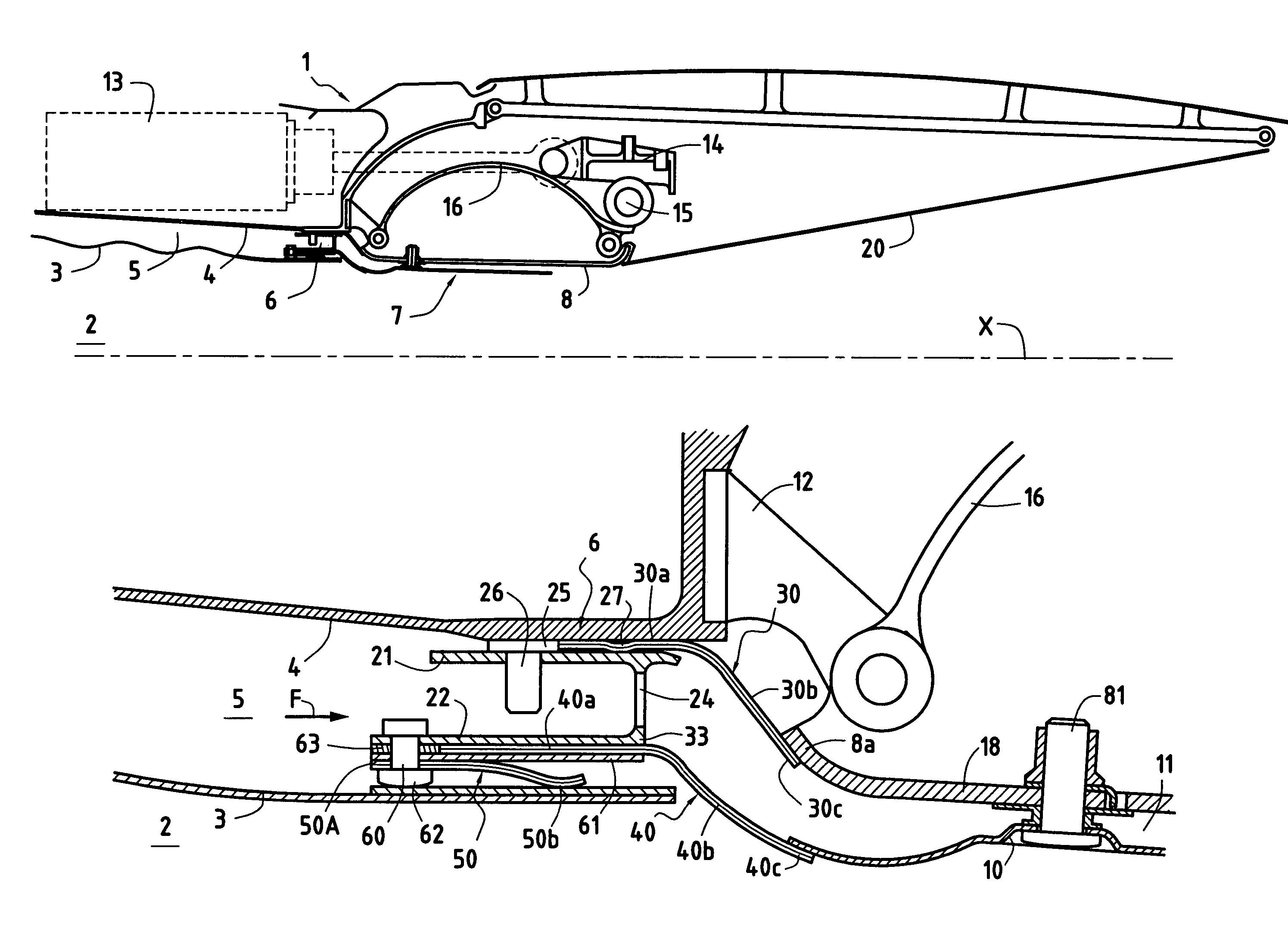
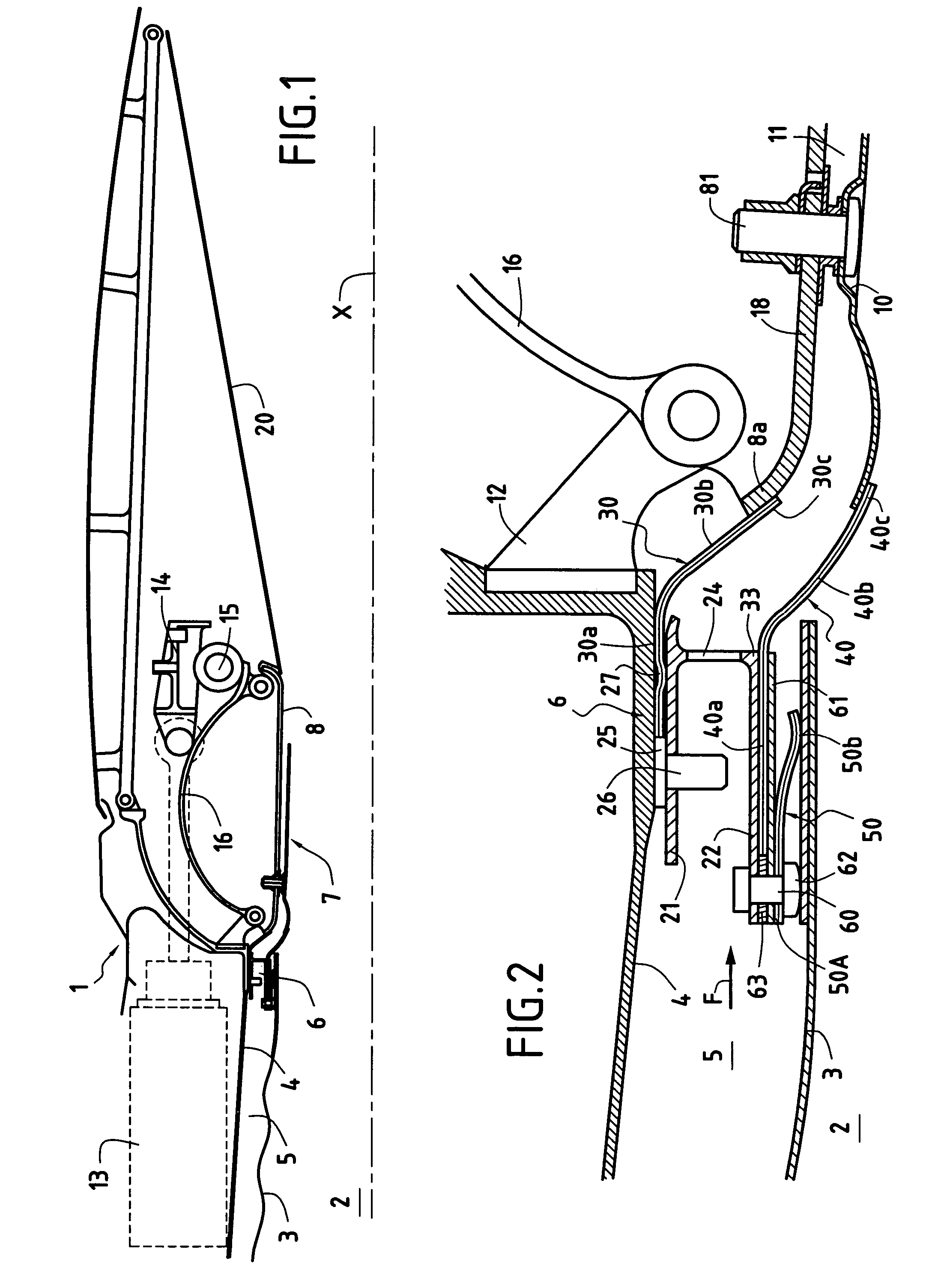
[0029]FIGS. 1 and 2 show the rear portion 1 of an aviation turbo-machine of axis X including, downstream from the turbine and not shown in the drawings, a post-combustion chamber 2 radially defined by a thermal protection lining 3, itself disposed inside an annular casing 4. Between them, the lining 3 and the casing 4 define an annular channel 5 in which there flows the secondary flow F and which includes at its downstream end a diaphragm 6 secured to the casing 4.

[0030]An axially symmetrical nozzle 7 is placed downstream from the post-combustion chamber 2.

[0031]This nozzle 7 compromises in particular a plurality of driven flaps 8 alternating with follower flaps 9 (see FIGS. 7 and 8) which present thermal protection plates 10 on their inside faces. Between them, the flaps 8 and 9 and the protection plates 10 define passages 11 for receiving the cooling air delivered by the diaphragm 6 to form a protective stream downstream from the thermal protection plates 10.

[0032]The flaps 8 and ...


PUM


Abstract

A turbomachine comprising, downstream from the turbine, a post-combustion chamber defined by a thermal protection lining inside a casing defining an annular channel for a secondary flow, an annular diaphragm secured at the downstream end of said channel, said nozzle comprising a plurality of flaps hinged to the upstream end of said casing, each flap fitted on its inside face with a thermal protection plate to define a passage for cooling air delivered by said diaphragm, wherein the cooling air is provided by an annular duct defined by a first flexible annular gasket in sliding contact against the downstream inside face of the casing and against the upstream inside faces of the flaps under the pressure of the secondary flow, and defined on the inside by a second flexible annular gasket whose upstream end is fixed to the radially inner zone of the diaphragm, and whose downstream end is in sliding contact against the upstream inside face of the protection plates.

Description

FIELD OF THE INVENTION[0001]The invention relates to problems of cooling the primary flaps of aviation turbomachines having a low dilution ratio and fitted with post-combustion chambers.[0002]More precisely, the invention relates to an aviation turbomachine comprising, downstream from the turbine, a post-combustion chamber extended by at least one nozzle, said chamber being defined radially by a thermal protection lining disposed inside a casing, said casing and said lining together defining an annular channel in which, in operation, there flows a secondary flow, an annular diaphragm secured to said casing being disposed at the downstream end of said channel, said nozzle comprising a plurality of flaps hinged to the upstream end of said casing, each flap being fitted on its inside face with a thermal protection plate co-operating with said flap to define a passage for being fed with cooling air delivered by said diaphragm.BACKGROUND OF THE INVENTION[0003]Modern military engines oper...

Claims


Application Information

Patent Timeline
Patent Type & Authority Patents(United States)
IPC IPC(8): F02K1/82F02K1/00F02K1/80F16J15/08F02C7/12F02C7/28F02C7/18F02C7/24
CPCF02K1/805F02K1/822F16J15/0887Y02T50/675F05D2260/10Y02T50/60F02C7/12
Inventor LAPERGUE, GUYSEVI, GUILLAUMEROCHE, JACQUES
Owner SN DETUDE & DE CONSTR DE MOTEURS DAVIATION S N E C M A
Why Eureka
Try Eureka