

Coolant demineralizer for a fuel cell vehicle
- Summary
- Abstract
- Description
- Claims
- Application Information
AI Technical Summary
Benefits of technology
Problems solved by technology
Method used
Image

Examples
Embodiment Construction
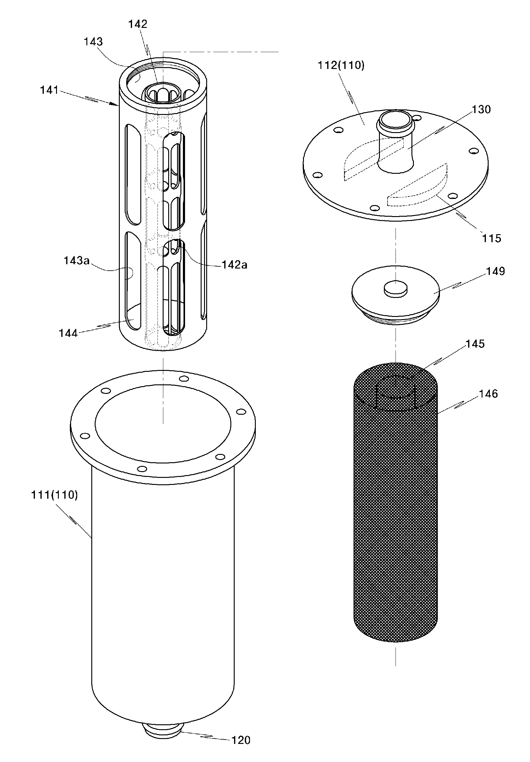
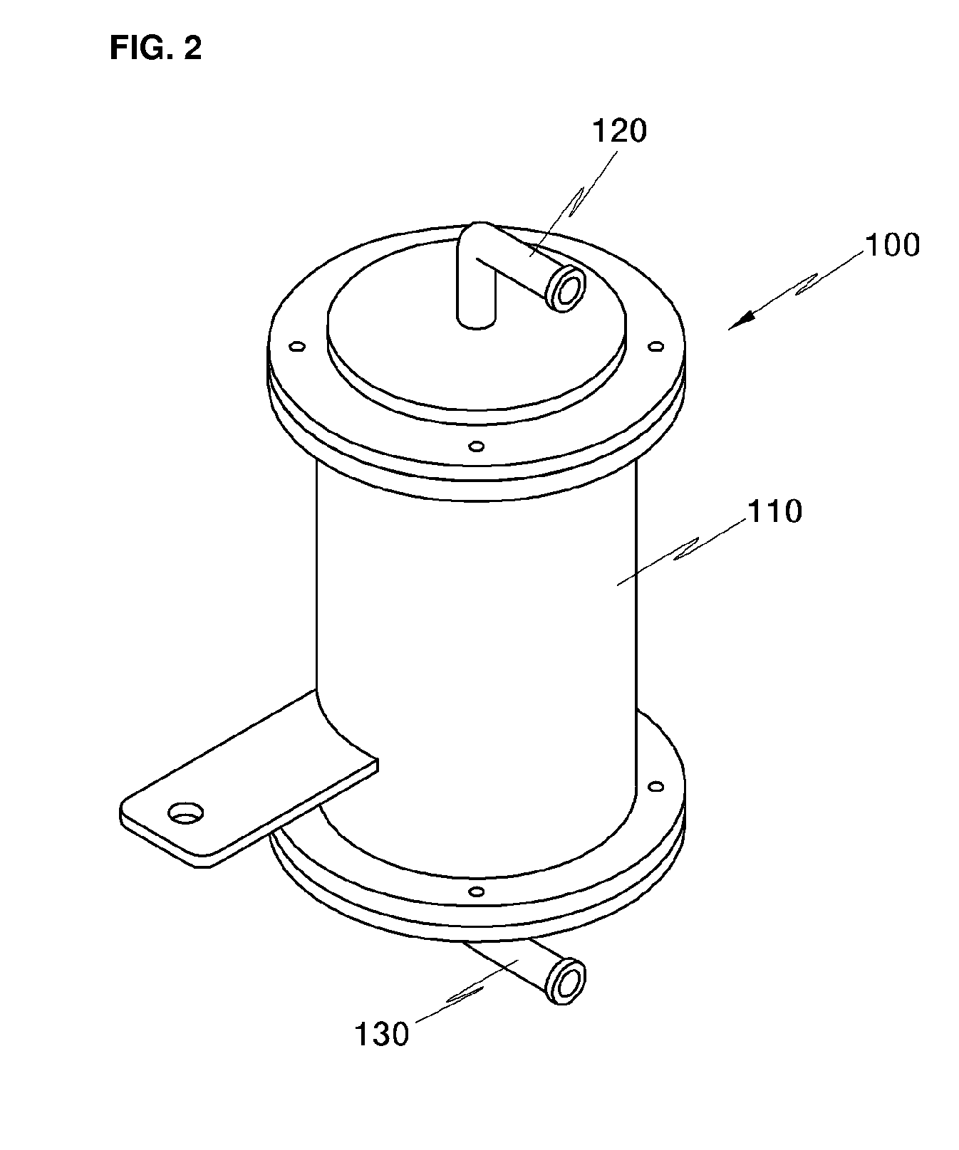
[0056]In one preferred aspect, the present invention features a coolant demineralizer for a fuel cell vehicle, the coolant demineralizer comprising a housing including an inlet port and an outlet port, a hollow filter member, in which an ion resin is filled, and a second flow chamber on the outside of the filter member.
[0057]In one embodiment, the hollow filter member comprises a first flow chamber mounted in the housing and connected to the inlet port of the housing.
[0058]In another embodiment, the second flow chamber is formed on the outside of the filter member in the housing and is connected to the outlet port such that coolant introduced into the first flow chamber through the inlet port passes through the filter member in a radial direction to be filtered and is then discharged through the second flow chamber and the outlet port.
[0059]In another further embodiment, the filter member comprises a plurality of coolant through holes formed on an inner surface of the filter member,...
PUM
| Property | Measurement | Unit |
|---|---|---|
| Pressure | aaaaa | aaaaa |
| Flow rate | aaaaa | aaaaa |
| Size | aaaaa | aaaaa |
Abstract
Description
Claims
Application Information