Inductive Signal and Energy Transfer through the External Auditory Canal

a technology of external auditory canal and inductive signal, which is applied in the direction of deaf-aid sets, electrical equipment, therapy, etc., can solve the problems of not being able to achieve uniform winding from the center to the outer radius, unable to achieve magnetic resonance imaging, and unable to achieve uniform size and shape, and inhibiting the production of cerumen

Active Publication Date: 2011-06-02
MED EL ELEKTROMEDIZINISCHE GERAETE GMBH
View PDF8 Cites 65 Cited by
  • Summary
  • Abstract
  • Description
  • Claims
  • Application Information

AI Technical Summary

Benefits of technology

[0009]There also may be an encapsulation layer of biocompatible material covering at least one of the coils. The encapsulation layer may include a substance that inhibits production of cerumen (ear wax). The encapsulation layer also may have ventilation openings for ventilation of the underlying skin. The ventilation openings may have a uniform size and shape, or they may be different sizes.
[0010]In some embodiments, the transmission wire loops may be concentrated at one or more radii from a central axis of the transm

Problems solved by technology

Hearing systems such as those described above are known to have various difficulties associated with the transmitter coil 107.
These magnets create problems with magnetic resonance imaging (MRI) or at the skin which covers t

Method used


Image

  • Inductive Signal and Energy Transfer through the External Auditory Canal
  • Inductive Signal and Energy Transfer through the External Auditory Canal
  • Inductive Signal and Energy Transfer through the External Auditory Canal

Examples


Embodiment Construction

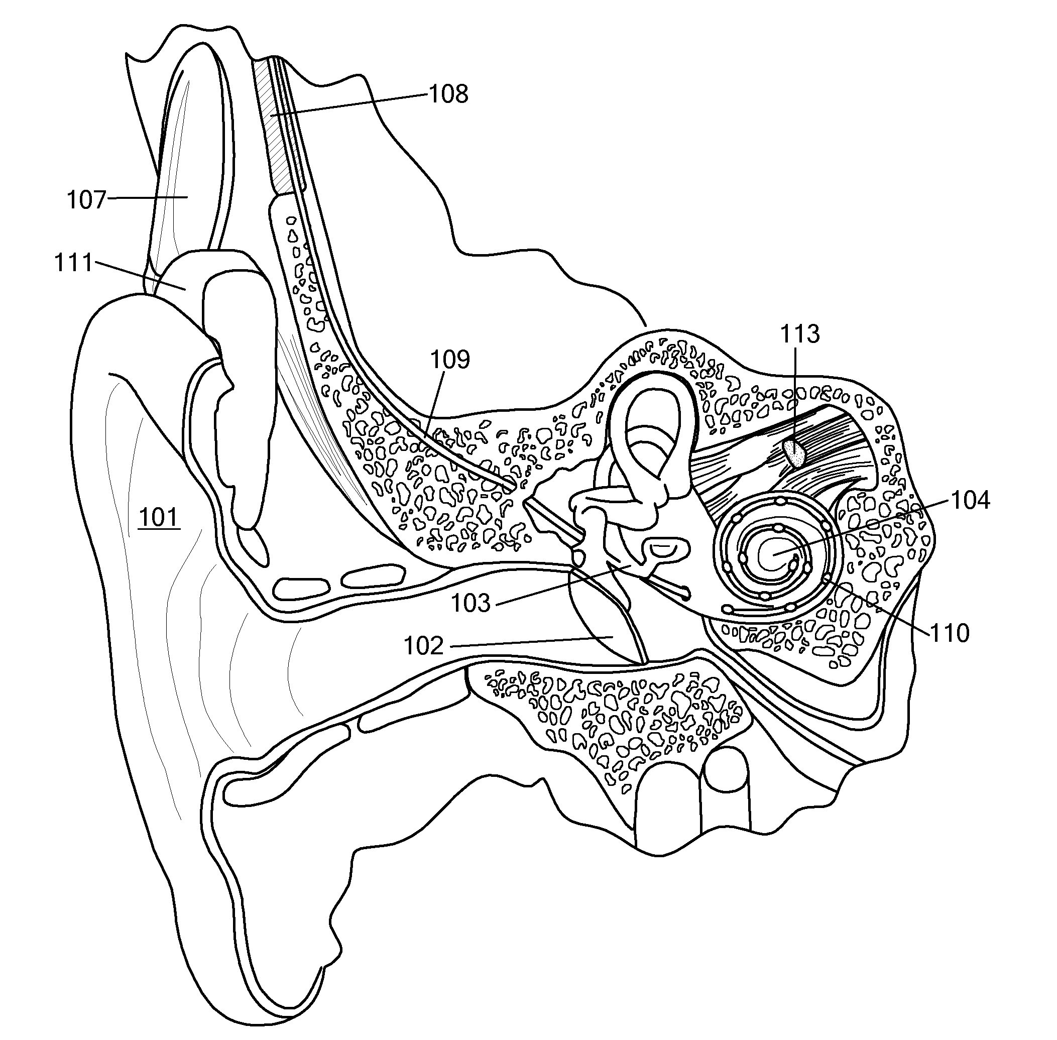
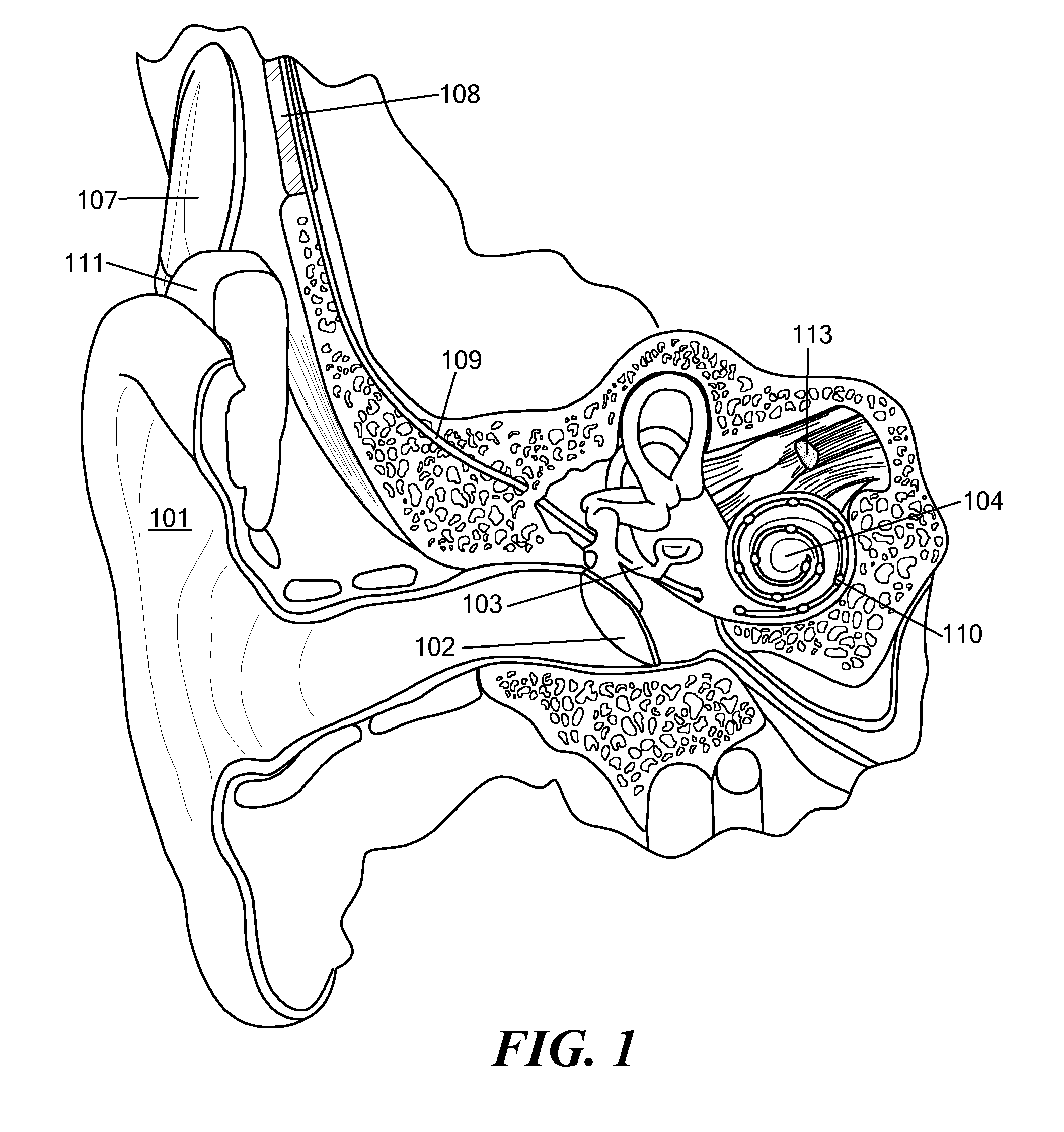
[0019]Partially implantable systems such as hearing implants (HI) include both external and implantable components. Hearing implants include, e.g., cochlear implants (CI's), middle ear implants (MEI's), bone conduction implants, etc. In such systems, transfer of electrical energy and data signals is based on an external primary coil (referred to as the transmitter coil) and an internal secondary coil (referred to as the receiver coil). Many partially and totally implantable medical systems also require regular charging cycles for their implantable batteries. Instead of the traditional transcutaneous inductive link located on the side of the head near the mastoid bone above and behind the pinna (outer ear) as with existing HI systems, embodiments of the present invention transfer energy and data signals inductively through the skin at the outer wall of the ear canal.

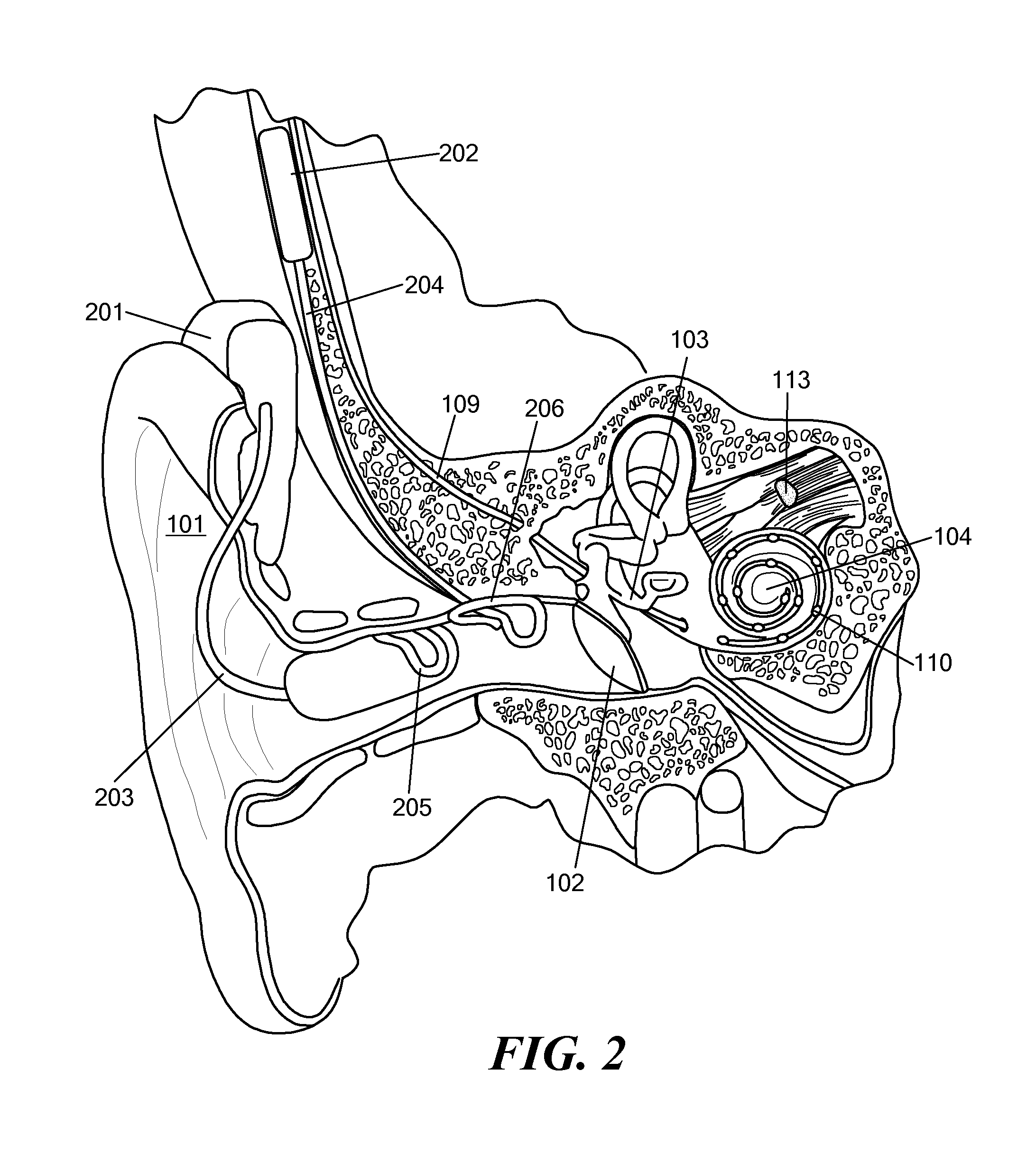
[0020]FIG. 2 shows an inductive coil arrangement for an ear canal of a recipient patient according to one embodiment of...


PUM


Abstract

An inductive coil arrangement is described for an ear canal of a recipient patient. An inner transmitter coil inserts into the ear canal for transmitting a communication signal through the skin of the outer wall of the ear canal. The transmitter coil includes transmission wire loops that lie substantially in a common plane which curves around the central axis of the ear canal conformal to the outer wall of the ear canal. An outer receiver coil is implantable under the skin of the outer wall of the ear canal for receiving the communication signal from the transmitter coil. The receiver coil includes receiver wire loops that lie substantially in a common plane which curves around the central axis of the ear canal substantially parallel to the transmitter coil.

Description

[0001]This application claims priority from U.S. Provisional Patent Application 61 / 265,399, filed Dec. 1, 2009, which is incorporated herein by reference.FIELD OF THE INVENTION[0002]The present invention relates to implantable medical devices, and more specifically to an inductive coil arrangement for such devices.BACKGROUND ART[0003]A normal ear transmits sounds as shown in FIG. 1 through the outer ear 101 to the tympanic membrane (eardrum) 102, which moves the bones of the middle ear 103, which in turn vibrate the oval window and round window openings of the cochlea 104. In response to received sounds transmitted by the middle ear 103, the fluid filled cochlea 104 functions as a transducer to generate electric pulses that are transmitted to the acoustic nerve 113, and ultimately to the brain. Hearing is impaired when there are problems in the ability to transduce external sounds into meaningful action potentials along the neural substrate of the cochlea 104.[0004]In some cases, he...

Claims


Application Information

Patent Timeline
IPC IPC(8): H04R25/00
CPCA61N1/08H04R25/606A61N1/37229A61N1/36032A61N1/36038
Inventor ILBERG, CHRISTOPH VON
Owner MED EL ELEKTROMEDIZINISCHE GERAETE GMBH
Why Eureka
Try Eureka