Uterus manipulator

a manipulator and uterus technology, applied in the field of uterus manipulators, can solve the problems of inadequate intrauterine cell suction, etc., and achieve the effect of simplifying the handling

Active Publication Date: 2011-06-02
RICHARD WOLF GMBH
View PDF9 Cites 41 Cited by
  • Summary
  • Abstract
  • Description
  • Claims
  • Application Information

AI Technical Summary

Benefits of technology

[0009]Due to the fact that the vaginal seal is formed by a sealing bell, which is open proximally and whose peripheral edge is designed for the sealed bearing on the vaginal wall, a common attachment of the components on the instrument is possible, but the required distance is simultaneously formed, this distance being required so that the sealing effect is maintained after severing the rear fornix.
[0010]Due to the fact that the suction bell ...

Problems solved by technology

However, it has been found that this intrauterine cell suctioning is inadequate, in particular with the previ...

Method used


Image

  • Uterus manipulator
  • Uterus manipulator
  • Uterus manipulator

Examples


Embodiment Construction

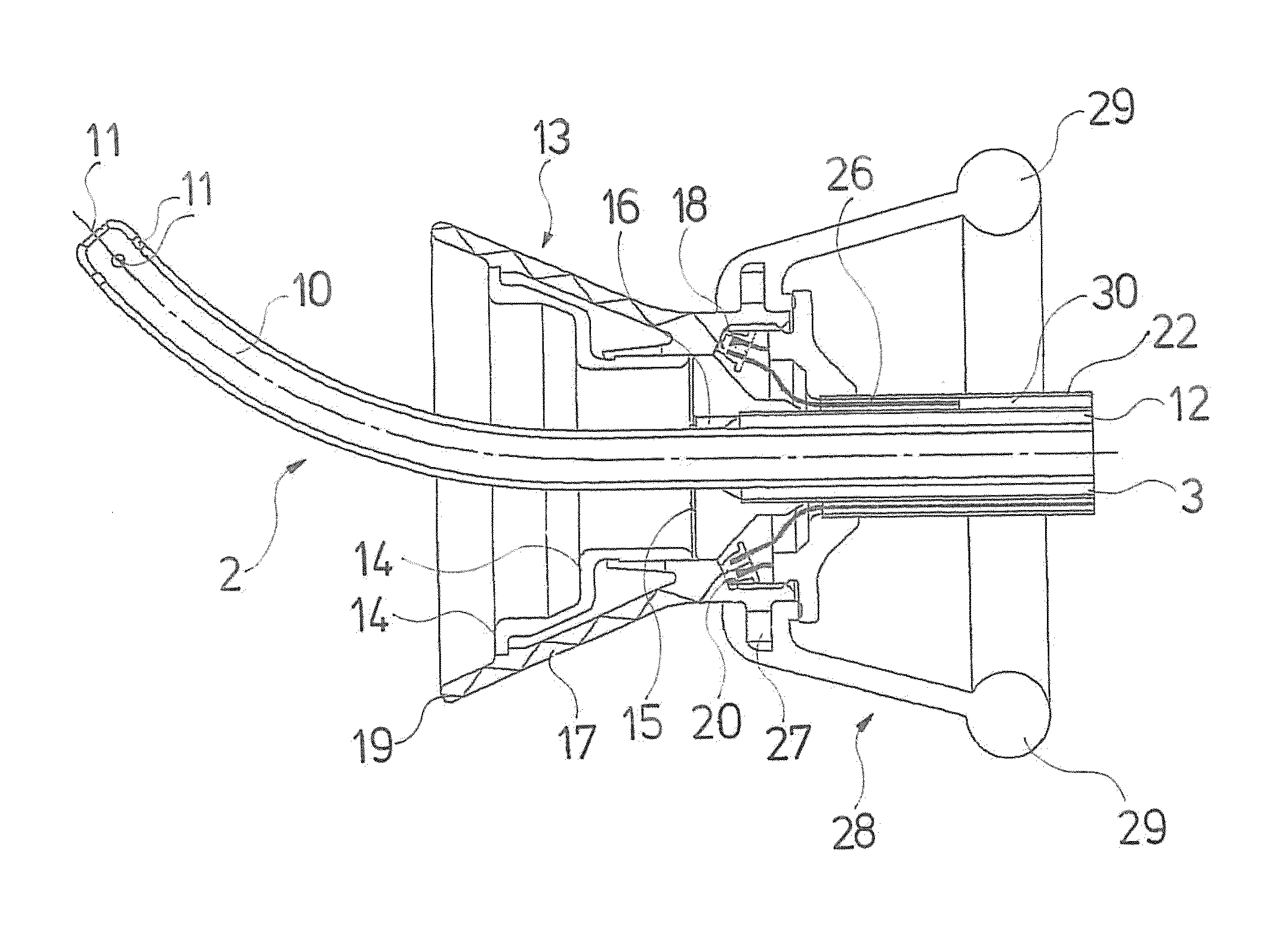
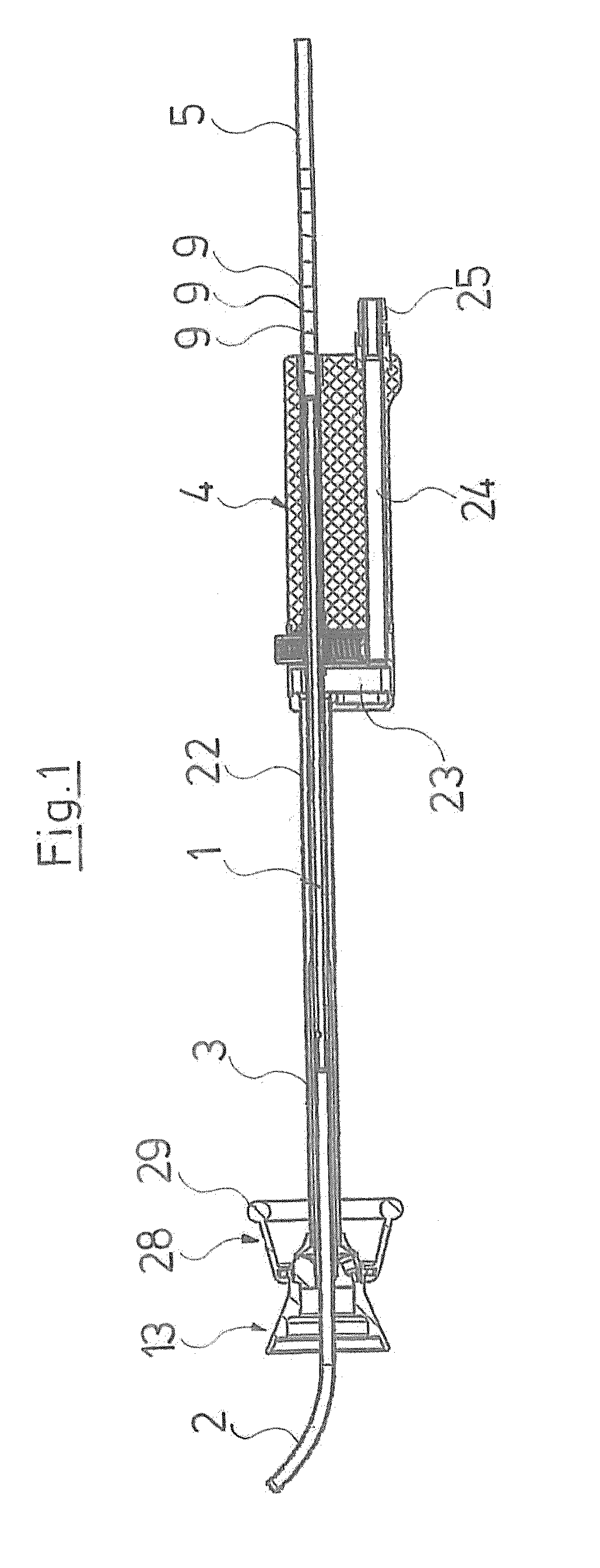
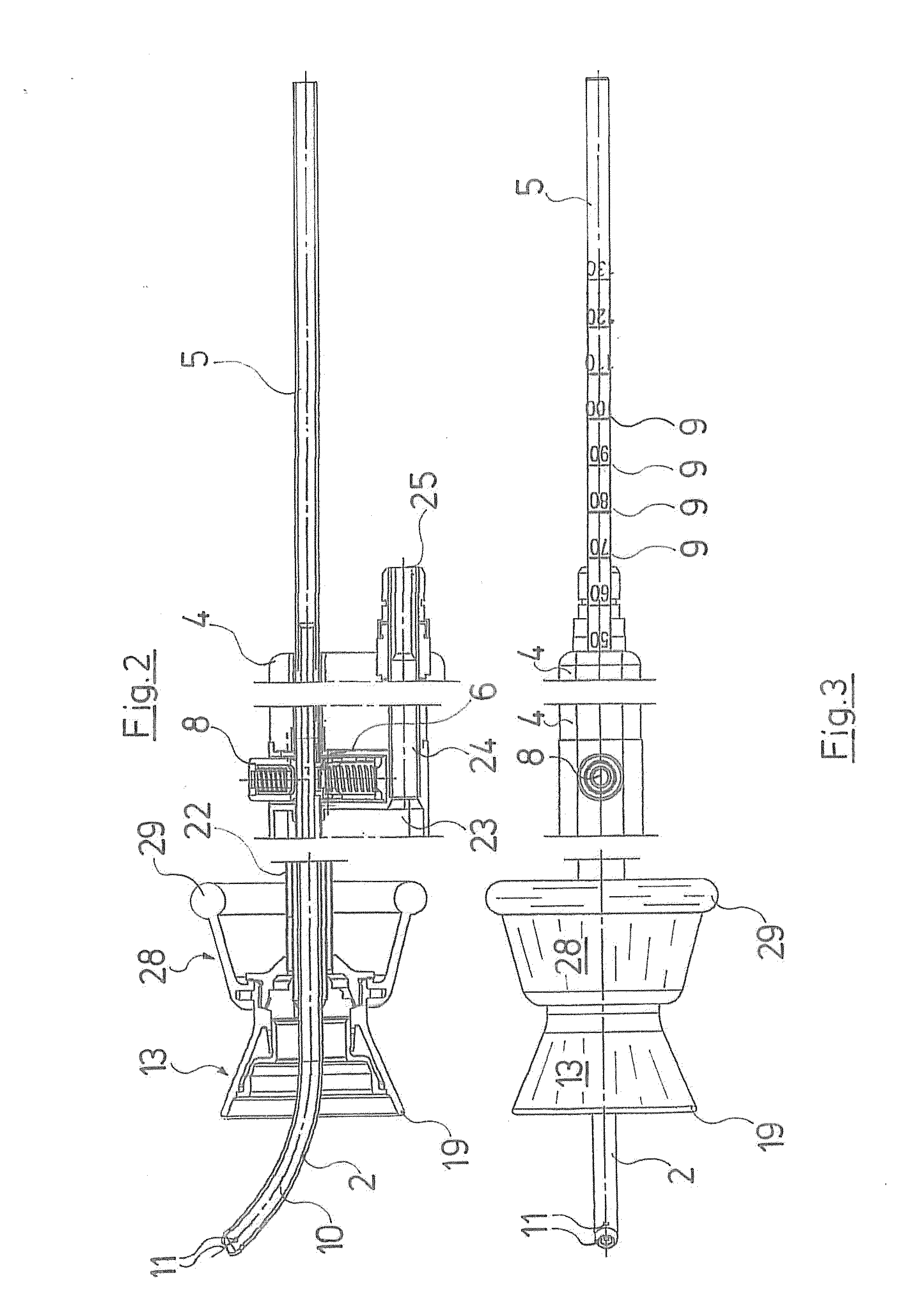
[0032]The uterus manipulator represented by the Figures comprises a hollow probe 1, which extends through the whole instrument and at the distal end forms a distal end section 2, which is envisaged for introduction into a uterus through the cervical canal. The hollow probe 1 extends from the distal end section 2 proximally through a shank 3, which is fastened proximally in a grip part 4 forming the handle of the instrument. The hollow probe 1 extends through the grip part 4 and comprises a proximal end section 5, which projects beyond the grip part 4 on the proximal side and is designed in a hollow manner there. The hollow probe 1, however, is connected to the grip part 4 in a rotationally fixed manner, but in a releasable manner in the axial direction.

[0033]The length of the distal end section 2, thus the length with which the hollow probe 1 distally projects beyond the shank 3, may be adjusted, in order to be able to adapt the instrument, in particular the mentioned length, to the...


PUM


Abstract

A uterus manipulator includes a shank, in which a hollow probe is guided, whose distal end section is envisaged and designed for introduction into a uterus through the cervical canal. A handle is provided on the proximal side. A distally open bell and a vaginal seal, arranged proximally displaced thereto, as well as a suction channel which connects to at least one suction opening in the distal end section, are provided for receiving a cervix. The bell is designed as a suction bell, wherein at least one suction channel runs into the bell.

Description

BACKGROUND OF THE INVENTION[0001]The invention relates to a uterus manipulator, in particular for laparoscopically assisted vaginal hysterectomy.[0002]With the combined operative removal of the uterus carried out laparoscopically and through the vagina (LAVH—laparoscopically assisted vaginal hysterectomy), one requires an instrument set which among other things comprises a uterus manipulator, with which the uterus from the outside, may be led through the vagina by a probe introduced through the cervical canal. Such a uterus manipulator is known for example from U.S. Pat. No. 5,520,698. This instrument, additionally to the probe, yet comprises a bell which is open at the distal end and which serves for receiving the cervix and improves the leading of the uterus through the instrument. The bell is provided with lateral openings. A vaginal seal is provided on the proximal side of the bell and at a distance to it and is formed by an inflatable balloon ring, which is to be applied in a s...

Claims


Application Information

Patent Timeline
IPC IPC(8): A61B17/42
CPCA61B17/4241A61B19/5202A61B2019/462A61B2017/306A61B2017/308A61B2017/00557A61B90/30A61B2090/062
Inventor BOEBEL, MANFREDWEBER, BERND CLAUSSOLIMA, EUGENIO
Owner RICHARD WOLF GMBH
Why Eureka
Try Eureka