
Monocular Light Source Positioning Device and Method for Stimulating Photoneuronic Response

a positioning device and light source technology, applied in the direction of sleep-inducing devices, radiation therapy, therapy, etc., can solve the problems of many other physical conditions, unsatisfactory mood disorders, etc., and achieve the effect of reducing interference such treatmen

Active Publication Date: 2011-06-02
GERARDO ERNESTO
View PDF14 Cites 4 Cited by
  • Summary
  • Abstract
  • Description
  • Claims
  • Application Information

AI Technical Summary

Benefits of technology

"The patent describes a monocular photoneuronic device that includes a support member that is held on the user's head and a housing that holds a battery and electronics. The device has a light source that can be adjusted to enter the user's eye at a comfortable level while providing sufficient light intensity to stimulate a photoendocrine response. The light source is a single narrow beam cyan LED mounted within a reflector body. The device can be held in place by ear clips or a curved ear grip support member. The device is simpler and more compact than previous devices. The technical effects of the patent are a comfortable and adjustable light source that does not interfere with the user's field of view."

Problems solved by technology

This failure can cause undesirable mood disorders and many other physical conditions.

Method used


Image

  • Monocular Light Source Positioning Device and Method for Stimulating Photoneuronic Response
  • Monocular Light Source Positioning Device and Method for Stimulating Photoneuronic Response
  • Monocular Light Source Positioning Device and Method for Stimulating Photoneuronic Response

Examples


first embodiment

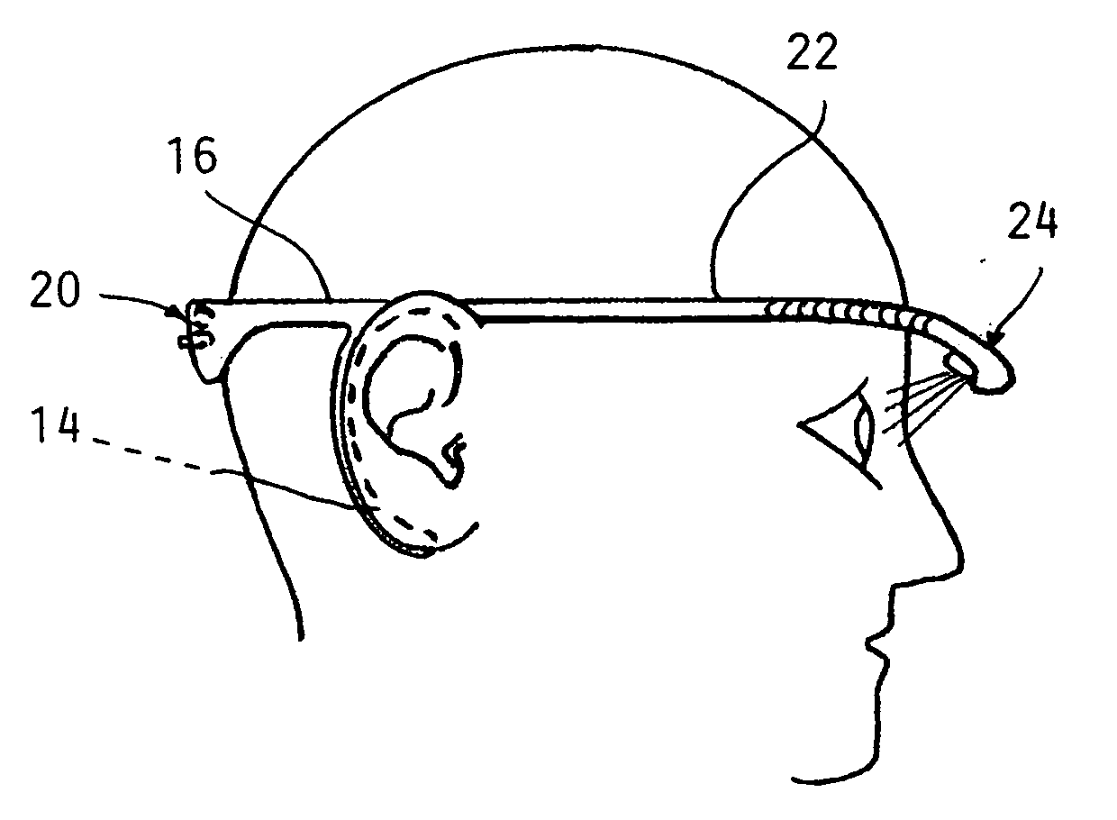
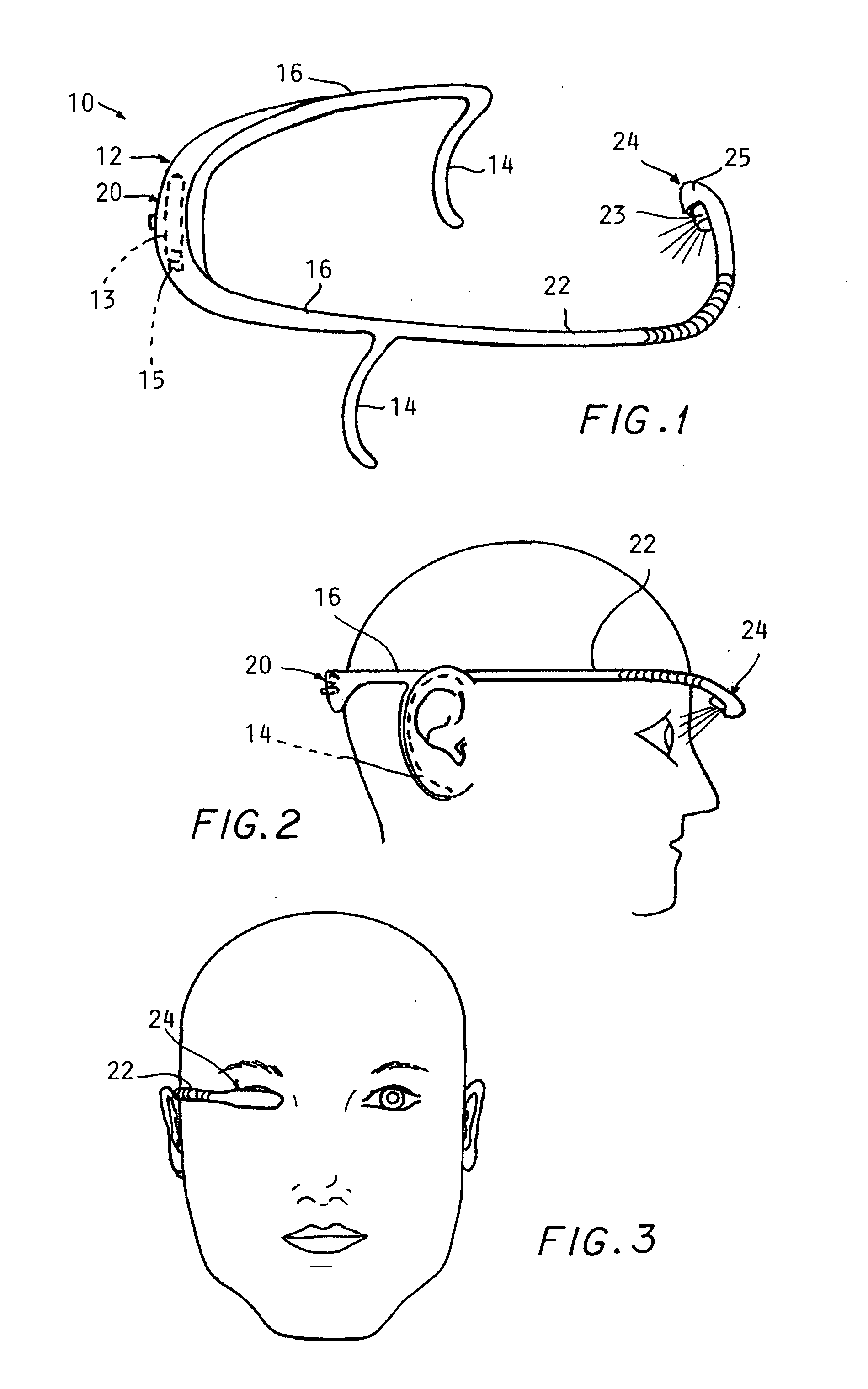
[0020]Referring to the drawings and in particular FIGS. 1-3, a monocular light source treatment device 10 is shown.

[0021]A U-shaped support member 12 has a curved ear clip 14 on each of the inwardly turned ends of each leg 16 of the support member 12 (FIG. 1). Hooking of one clip 14 behind each ear secures the support member 12 in position extending around the rear of a wearer's head as seen in FIG. 2.

[0022]The rear of U-shaped member 12 mounts housing 20 containing a battery 13 and associated electronics 15. An on-off switch 21 is also provided on the housing 20. These components may be of conventional design, as suitable components are readily available.

[0023]Projecting from one side of the support member 12 is an easily bendable but self supporting elongated light support element 22 which supports and also transmits power from the battery 13 to a light source 24. This element may comprise bendable electrical cables encased in an insulating plastic.

[0024]The light source 24 prefer...

second embodiment

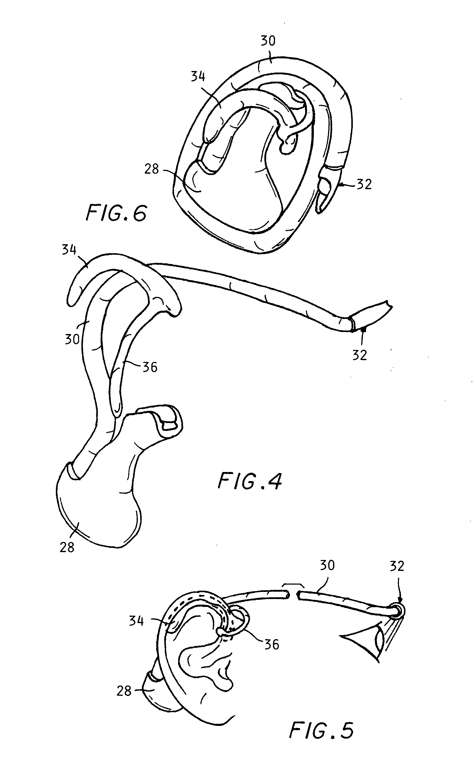
[0032]Referring to FIGS. 4-6, a monocular light source positioning device 26 is shown which is supported by a single ear of a wearer.

[0033]Device 26 comprises a molded plastic assemblage including a bulbous housing 28 having an elongated readily bendable light source support element 30 projecting therefrom. A compact LED assembly 32 is mounted at the free end thereof to be readily positionable by bending element 30 as necessary.

[0034]A support piece 34 is attached by a second elongated element 30 to the elongated light source support element 30.

[0035]The support piece 34 (which may be bendable) is fit around the antihelix fold of the wearer's ear as indicated in FIG. 5.

[0036]This allows the housing 28 to be held behind the wearer's ear with the element 30 extending alongside his or her head and bent around to a position above the eye (or directly in front of the eye as shown in FIG. 3).

[0037]Accordingly, the compact devices described are effective in producing a photoendocrine respo...


PUM


Abstract

A monocular light source positioning device includes a support member which held on the head of a user to hold an elongated readily bendable but self supporting element having a light source effective to stimulate a photo-endocrine response attached at a free end thereof positioned over or in front of only one eye of the person to provide a method of stimulating a photoendocrine response without interfering with the principal field of view of the user.

Description

CROSS REFERENCE TO RELATED APPLICATIONS[0001]This application claims the benefit of U.S. provisional 61 / 265,960 filed on Dec. 2, 2009, incorporated herein by reference.BACKGROUND OF THE INVENTION[0002]This invention concerns the use of light to stimulate a photo-endocrine response within the human optic-endocrine axis. This response may be used to treat numerous conditions, such as Seasonal Affective Disorder, Jet Lag, and many other conditions now believed to respond to light therapy. These conditions are thought to involve a failure of person's body to maintain a proper circadian rhythm which is regulated by daily exposure of the retinas to light of a specific color wavelength range. This failure can cause undesirable mood disorders and many other physical conditions. Various devices have been developed for treating these conditions, including light boxes before which a person stands for particular time periods on a daily basis.[0003]The desirability of allowing a user to move abo...

Claims


Application Information

Patent Timeline
Patent Type & Authority Applications(United States)
IPC IPC(8): A61N5/06
CPCA61M21/00A61M2021/0044A61N2005/0662A61N2005/0648A61N2005/0651A61N5/0618
Inventor GERARDO, ERNESTO A.
Owner GERARDO ERNESTO
Learn More