Manual surveying instrument having collimation assisting device

a technology of collimation assisting device and manual surveying instrument, which is applied in the direction of instruments, optical elements, optics, etc., can solve the problems of difficult even for experienced observers, observer can only perform highly erroneous measurements, so as to achieve even easier collimation operation, easy collimation operation, and easy collimation operation

Inactive Publication Date: 2011-06-09
KK TOPCON
View PDF7 Cites 28 Cited by
  • Summary
  • Abstract
  • Description
  • Claims
  • Application Information

AI Technical Summary

Benefits of technology

[0025]Because the manual surveying instrument according to the first aspect of the present invention includes a collimation assist device having a collimation light transmitting system that emits a collimation light along a collimation axis toward a target installed at a measurement point, an area sensor that obtains an image of a scene captured within a field of view of a collimating telescope, a display unit that displays the image, a collimation light detecting unit that detects the target as a result of receiving the collimation light reflected on the target by the area sensor, and an arithmetic control unit that displays an area indicating being within a predetermined deviation from the collimation axis and a symbol indicating the target on the display unit as an animation image, judges that collimation has been completed when the target has been captured, by a manual operation of the collimating telescope, within the area indicating being within a predetermined deviation from the collimation axis to perform an angle measuring operation, and corrects an angle measurement value according to a deviation from the collimation axis of the target, the observer can observe the animation image on the display unit with both eyes while collimating the target, even somewhat imperfect collimation will suffice, and a high-precision angle measurement can be swiftly performed by an easy collimating operation.
[0026]In the second aspect of the present invention, further, the animation image is displayed with a deviation from the collimation axis enlarged as it approaches the collimation axis, and thus the collimating operation is even easier.
[0027]In the third aspect of the present invention, further, the symbol indicating the target changes in color, shape, or color and shape when having entered into the area indicating being within a predetermined deviation from the collimation axis, and thus the completion of collimation is found, and the collimating operation is even easier.
[0028]In the fourth aspect of the present invention, further, the symbol indicating the target changes in color, shape, or color and shape when the target has exited the field of view of the collimating telescope, and indicates a direction to return the collimating telescope, and thus it can be immediately found that the target has exited the field of view of the collimating telescope, and an operation to return the target into the field of view of the collimating telescope can be promptly performed, so that the collimating operation is even easier.
[0029]In the fifth aspect of the present invention, further, the symbol indicating the target changes in color, shape, or color and shape when the collimation light reflected from the target is excessively weak or excessively strong, and thus it can be known in advance that measurement with sufficient precision is not possible.
[0030]The sixth aspect of the present invention further includes a wide-angle digital camera separate from an optical system of the collimation telescope, in which the arithmetic control unit first displays an image obtained from the wide-angle digital camera on the display unit, displays the field of view of the collimating telescope on the display unit, and switches the image obtained from the wide-angle digital camera to the animation image when having judged that the target has been captured within the field of view of the collimating telescope, and thus the target can be swiftly captured within the field of view of the collimating telescope, the collimating operation is even easier, and a swift measurement is enabled.

Problems solved by technology

Meanwhile, in the above-mentioned manual surveying instrument, collimation errors according to observer proficiency have existed, and in the case of an inexperienced observer, there has been a problem that the observer can perform only highly erroneous measurements even by use of a valuable high-precision surveying instrument.
Moreover, there has also been a problem that, in an atmosphere with much shimmering such as heat haze, it is difficult even for an experienced observer to perform an accurate collimation, and the observer can perform only highly erroneous measurements.

Method used


Image

  • Manual surveying instrument having collimation assisting device
  • Manual surveying instrument having collimation assisting device
  • Manual surveying instrument having collimation assisting device

Examples


Embodiment Construction

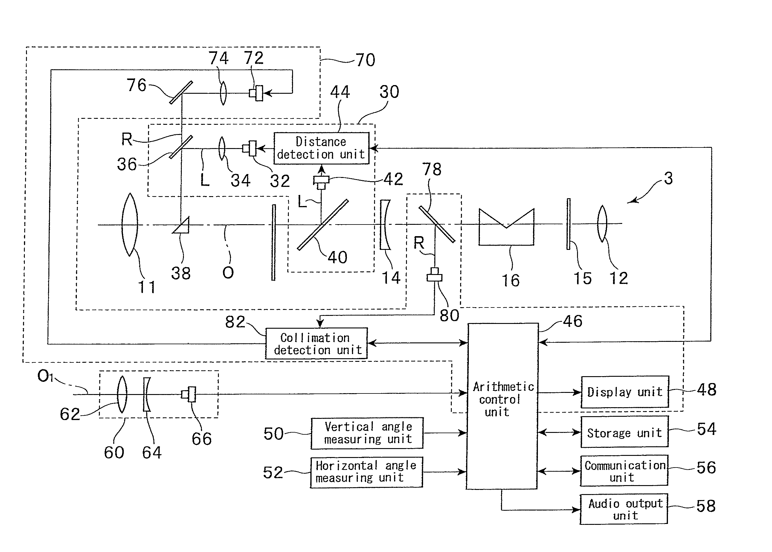
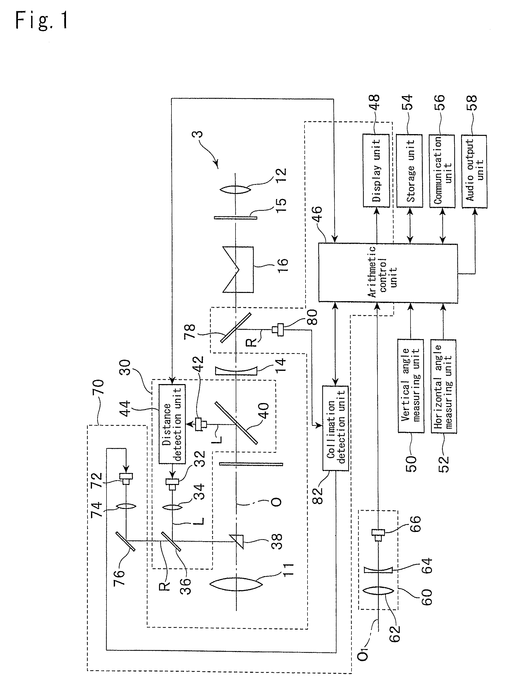
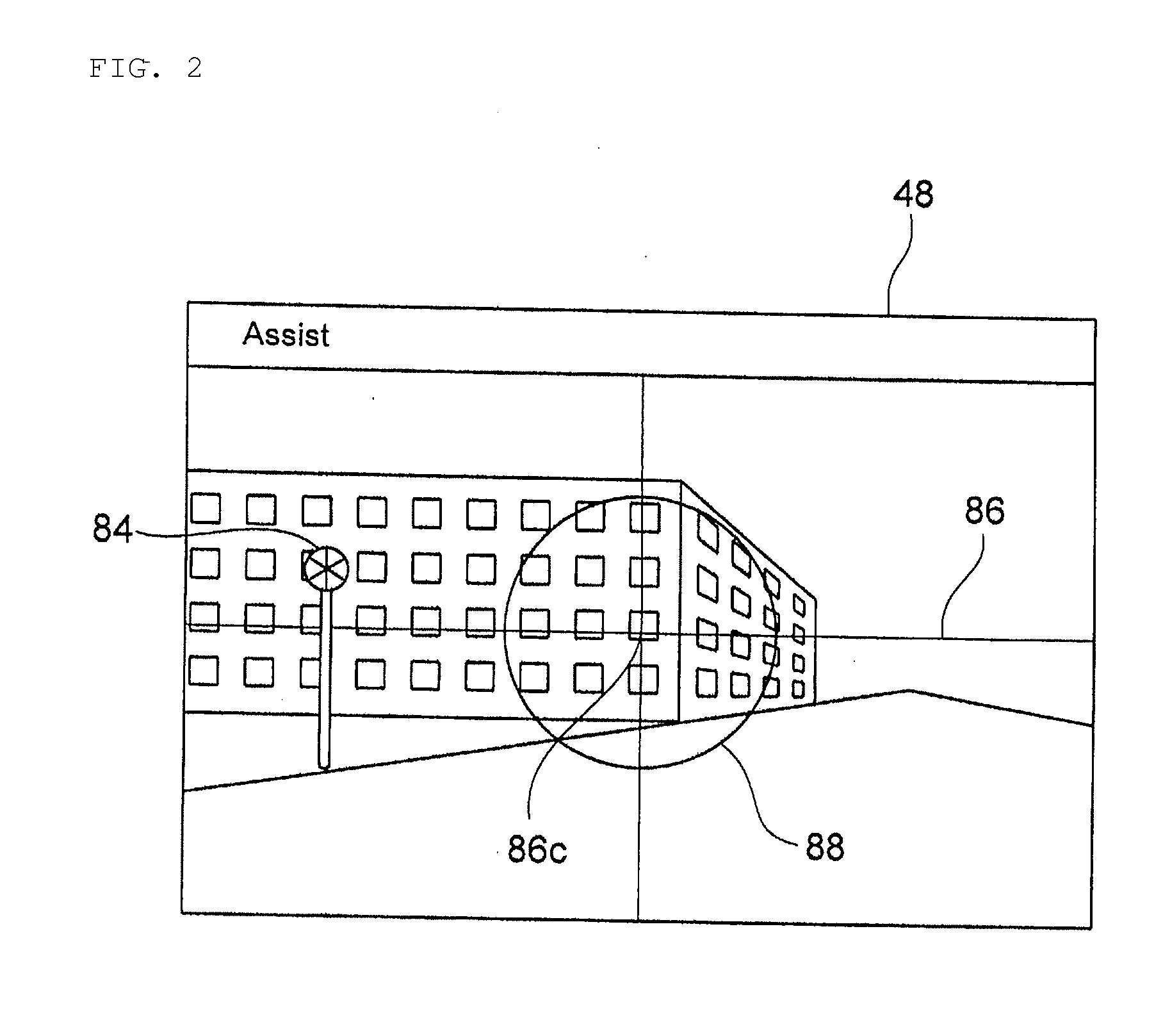
[0053]Hereinafter, by taking a total station, for example, as a manual surveying instrument (hereinafter, described simply as a surveying instrument) according to a first embodiment of the present invention, a preferred embodiment of the present invention will be described in detail with reference to the accompanying drawings. FIG. 1 is a block diagram of the surveying instrument. FIG. 2 is a view showing a state where an image captured by a wide-angle digital camera is displayed on a display unit. FIGS. 3 are views each showing a state where an animation image to facilitate manual collimation is displayed on the display unit.

[0054]As shown in FIG. 1, the surveying instrument includes, as a collimating telescope 3 for manual collimation, an objective lens 11, a focusing lens 14, an erecting prism 16, a focusing glass 15, and an eyepiece 12 on a collimation axis O. An observer can perform manual collimation by looking through the eyepiece 12.

[0055]Moreover, the surveying instrument i...


PUM


Abstract

[Problem] To provide a manual surveying instrument that allows easily performing a collimating operation and allows performing a high precision measurement in a short time,
[Solution Means] The manual surveying instrument includes a collimation assist device (70) having a collimation light transmitting system that emits a collimation light (R) along a collimation axis (O) toward a target installed at a measurement point, an area sensor (80) that obtains an image of a scene captured within a field of view of a collimating telescope (3), a display unit (48) that displays the image, a collimation light detecting unit (82) that detects the target as a result of receiving the collimation light reflected on the target by the area sensor, and an arithmetic control unit (46) that displays an area (94) being within a predetermined deviation from the collimation axis and where distance measurement is possible and a symbol indicating the target on the display unit as an animation image, judges that collimation has been completed when the target has been captured, by a manual operation of the collimating telescope, within the area where distance measurement is possible to perform a distance and angle measurement, and corrects an angle measurement value according to a deviation from the collimation axis of the target.

Description

TECHNICAL FIELD[0001]The present invention relates to a manual surveying instrument (mainly, a total station) including a collimation assist device that facilitates a collimating operation of the manual surveying instrument. The total station includes a distance measuring unit by a laser beam, an angle measuring unit, a collimating telescope unit, and a leveling unit, and measures the distance and azimuth angle up to a survey point.BACKGROUND ART[0002]In the above-mentioned manual surveying instrument, a collimating operation is necessary at the time of measurement so that a target such as a prism is located on a collimation axis. The collimating operation is to turn the collimating telescope around so as to be trained upon the target, capture the target within a field of view of the collimating telescope, and align, by means of a coarse and fine motion mechanism provided in the surveying instrument, the target with the center (collimation axis) of crosshairs observed within the fie...

Claims


Application Information

Patent Timeline
Patent Type & Authority Applications(United States)
IPC IPC(8): G01C5/00
CPCG01C15/00G01C15/002G01B9/06G02B23/00G02B27/30
Inventor YANOBE, SATOSHINAKAMURA, YUTAKA
Owner KK TOPCON
Why Eureka
Try Eureka