Connecting System For Surface Coverings

a technology of connecting system and surface covering, which is applied in the field of surface covering, can solve the problems of difficult connection of the other side edges of the plank with yet another similar plank, difficult to connect the edge portions of the plank with another similar plank, and disadvantages of current floor systems, so as to improve the ease of installation, facilitate the connection, and enhance the effect of pullout strength

Active Publication Date: 2011-06-09
MANNINGTON MILLS
View PDF47 Cites 92 Cited by
  • Summary
  • Abstract
  • Description
  • Claims
  • Application Information

AI Technical Summary

Benefits of technology

[0003]Laminate flooring usually has at least a core of particle or fiberboard or other wood-type material, an upper decorative surface layer, and a lower balancing layer of polymer or paper, or like material. The surface layer provides appearance and durability to the floorboards. The core provides stability, and the balancing layer keeps the board plane when the relative humidity (RH) varies. The floorboards are generally laid floating, i.e., without gluing, on an existing subfloor. Conventional floating flooring of this type are usually joined by means of a tongue-and-groove joints (i.e., joints involving a tongue on one floorboard and a tongue groove on an adjoining floorboard) on the long side and the short side that are mechanically locked in place. When laying the floor, the boards are brought together horizontally, whereby a projecting tongue along the joint edge of one board is introduced into a groove along the joint edge of an adjoining board. The same method is used on the long side as well as on the short side. Various types of glueless mechanical locking systems (including straight tongue and groove arrangements) have been utilized in the flooring industry. Flooring with glueless mechanical locking systems (tongue and groove arrangements) are becoming increasingly popular, as they are easy to lay, and, thus, it is not necessary to utilize highly trained personnel to lay such floor tiles.
[0018]Also, a feature of the present invention is to provide a flooring system that includes a foolproof installation design and technique to prevent installation errors.

Problems solved by technology

Current floor systems have suffered, however, from disadvantages.
One disadvantage experienced with current floor systems is that if each of the side edges of a plank includes a mechanical locking tongue or groove, once one of the side edges is connected to another similar plank, it is difficult to connect the other side edges of the plank with yet another similar plank.
This problem particularly accentuates itself while installing a click system floor in a very limited-free-space and / or confined area such as in corners of a room, under or around a door jamb, or under or around closets or kitchen islands, and the like.
In addition, the groove edge design of many conventional planks having a wood or wood-based core require the edge portions of the plank to be cut very thin.
The thin edge portions of these planks render the planks more vulnerable to damage during shipping and handling.
Once the edge of the plank is damaged, the plank cannot be effectively attached to other planks and is thereby rendered useless.
Also, certain groove edge designs are difficult to machine on wood or wood based materials.
Oftentimes, it is difficult to precisely shape a groove profile for wood or wood-based materials in a production line.
Thus, there are a limited number of groove designs which are available and effective for the edges of wood or wood-based planks.
For example, the straight side edges that are connected to one another may not be water tight and could potentially slide open to form a gap.
If an adhesive is used, the adhesive can be pressed out of the seams and create messy seams.
The integrity of such systems, however, is questionable and there is difficulty in making such a joint.

Method used


Image

  • Connecting System For Surface Coverings
  • Connecting System For Surface Coverings
  • Connecting System For Surface Coverings

Examples


Embodiment Construction

[0044]In the present invention, it is understood that the various embodiments shown in the Figures are illustrative, and unless indicated otherwise are not necessarily drawn to scale. Further, any dimensions given for various structural features are for illustrative purposes only, and are in no way intended to limit the scope of the present invention.

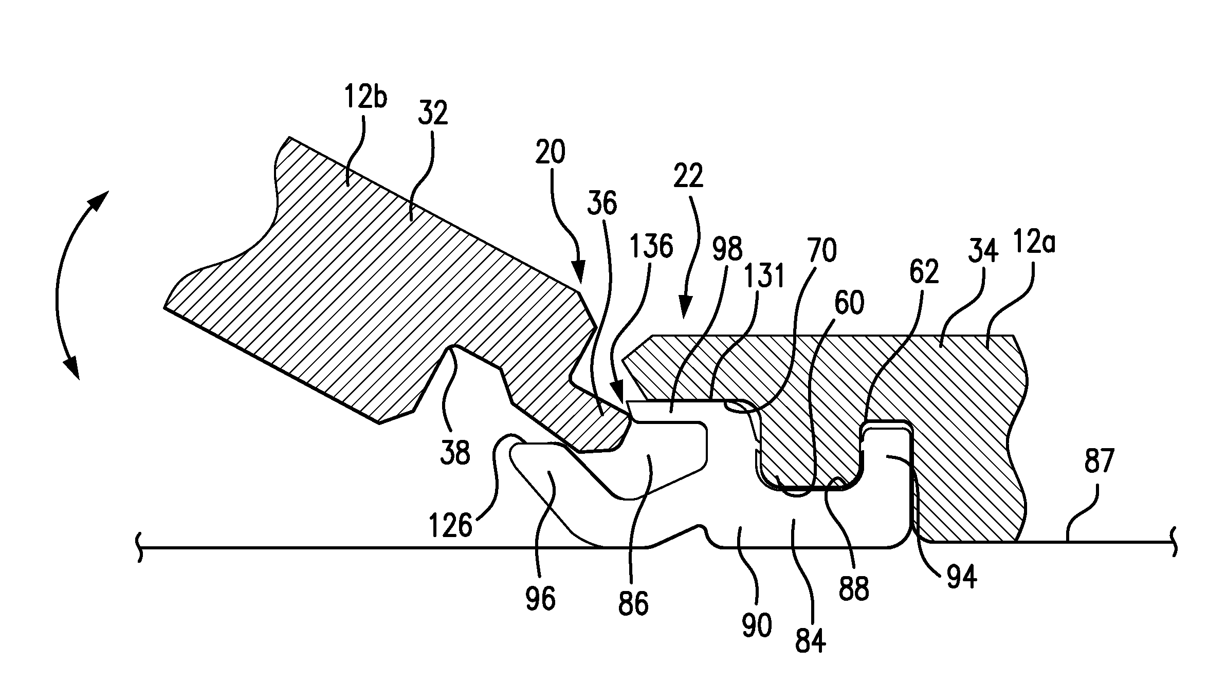
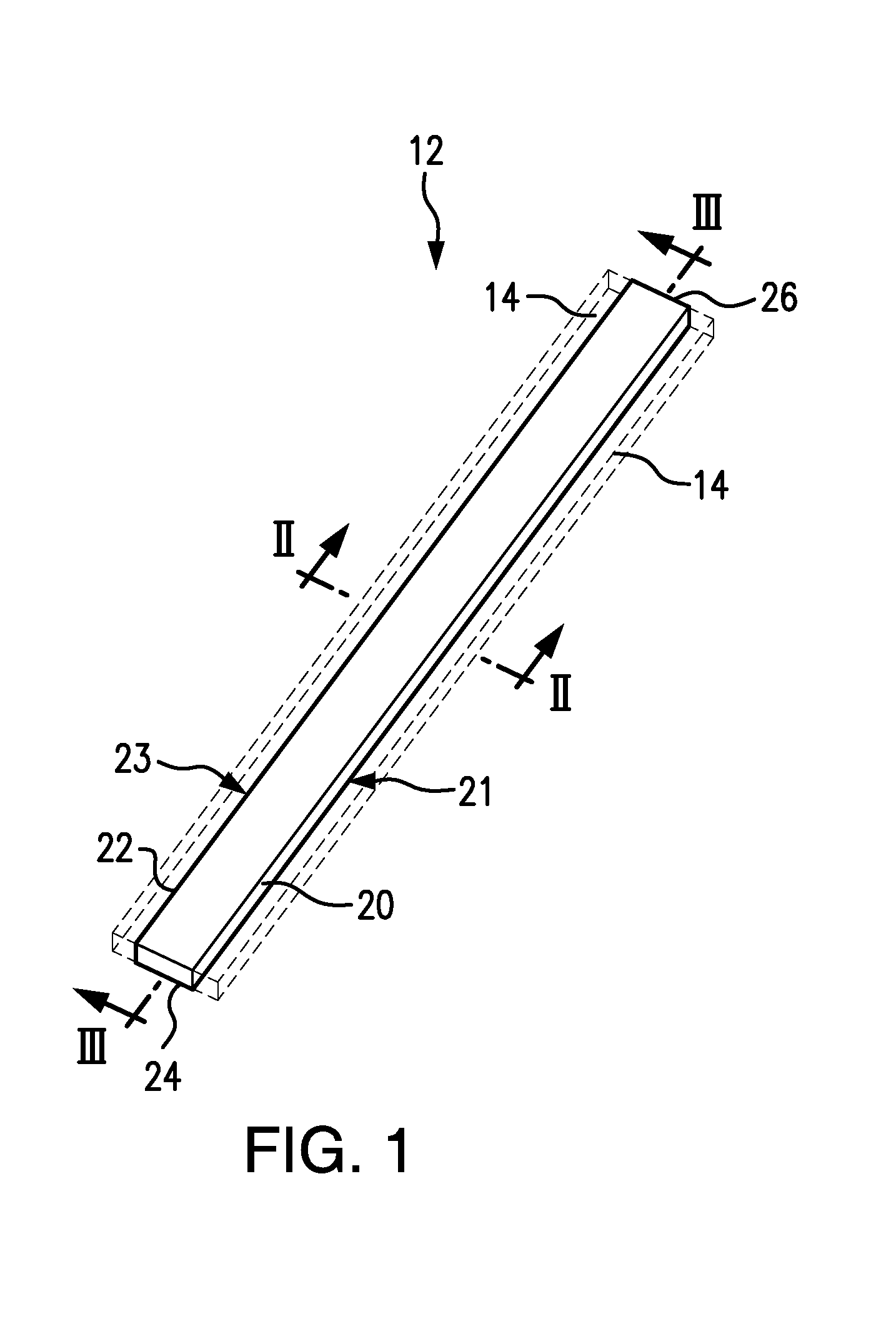
[0045]The present invention relates to a surface covering system having a plank including mechanically mating features defined in opposite edges and a connector configured to provide unique connection systems. The plank can be assembled in a modular detachable manner with other similarly configured planks to provide surface-coverings that are convenient to install and that have enhanced drift-resistance and other beneficial performance.

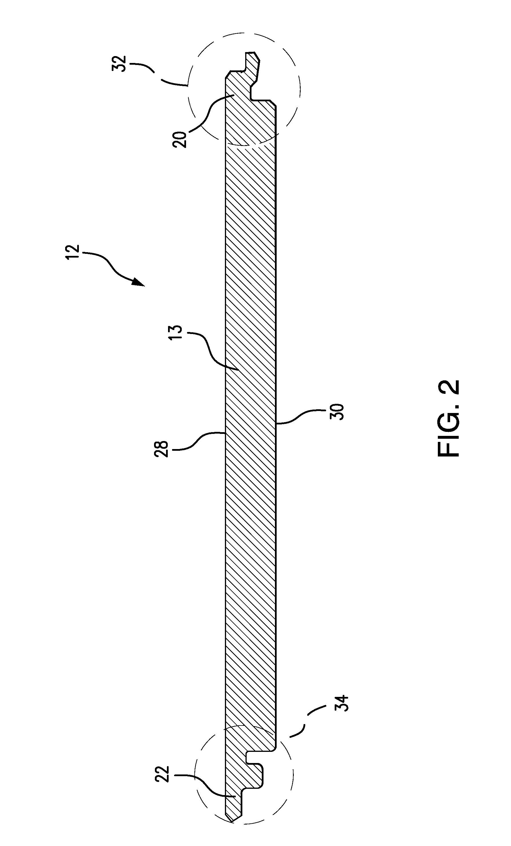
[0046]The plank of the present invention can comprise a plank that includes a tongue profile extending along a first edge of the plank, a downwardly extending rib profile extending along a second edge opp...


PUM


Abstract

A plank, and system and method for joining surface-covering planks, which includes a disengageable connector(s) for detachably connecting multiple planks simultaneously are described. A plank can include a tongue-profiled edge and an opposite rib-profiled edge, and a disengageable connector can have a groove that can be mated with the tongue on one side edge of the plank, and also has a rib-receiving portion that alternatively can be mated with a downward extending rib on the opposite side edge of the plank. The plank can have a variety of designs on the other edges of the plank.

Description

BACKGROUND OF THE INVENTION[0001]This application claims the benefit under 35 U.S.C. §119(e) of prior U.S. Provisional Patent Application No. 61 / 266,534, filed Dec. 4, 2009, which is incorporated in its entirety by reference herein.[0002]The present invention relates to surface-coverings, like flooring, and methods of installing the same.[0003]Laminate flooring usually has at least a core of particle or fiberboard or other wood-type material, an upper decorative surface layer, and a lower balancing layer of polymer or paper, or like material. The surface layer provides appearance and durability to the floorboards. The core provides stability, and the balancing layer keeps the board plane when the relative humidity (RH) varies. The floorboards are generally laid floating, i.e., without gluing, on an existing subfloor. Conventional floating flooring of this type are usually joined by means of a tongue-and-groove joints (i.e., joints involving a tongue on one floorboard and a tongue gr...

Claims


Application Information

Patent Timeline
Patent Type & Authority Applications(United States)
IPC IPC(8): E04B5/00E04C2/38E04B1/61
CPCE04F15/02E04F2201/0107E04F2201/0517E04F2201/0505E04F2201/0153
Inventor CHEN, HAO A.WHISPELL, JOHN M.
Owner MANNINGTON MILLS
Why Eureka
Try Eureka