

Method and apparatus for controlling electric servo press
a technology of electric servo press and control method, which is applied in the direction of press ram, electric programme control, manufacturing tools, etc., can solve the problems that the control accuracy in the most frequently used area is low, and the press working with high accuracy cannot be satisfactorily realized, etc., to achieve high accuracy, simple and low-cost configuration, and generate a large pressure force
- Summary
- Abstract
- Description
- Claims
- Application Information
AI Technical Summary
Benefits of technology
Problems solved by technology
Method used
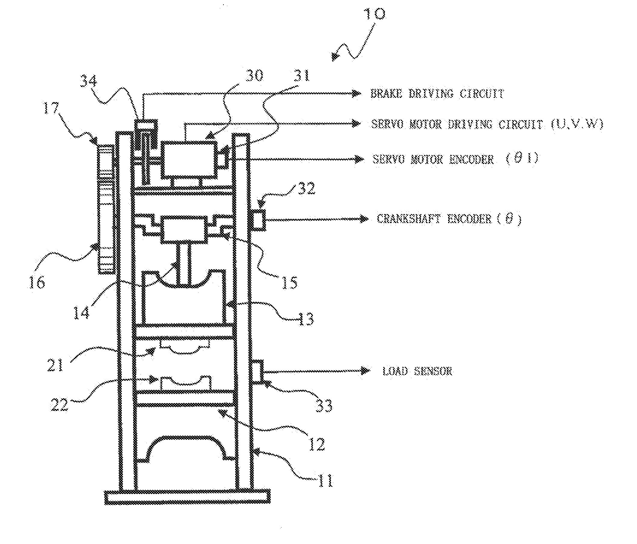
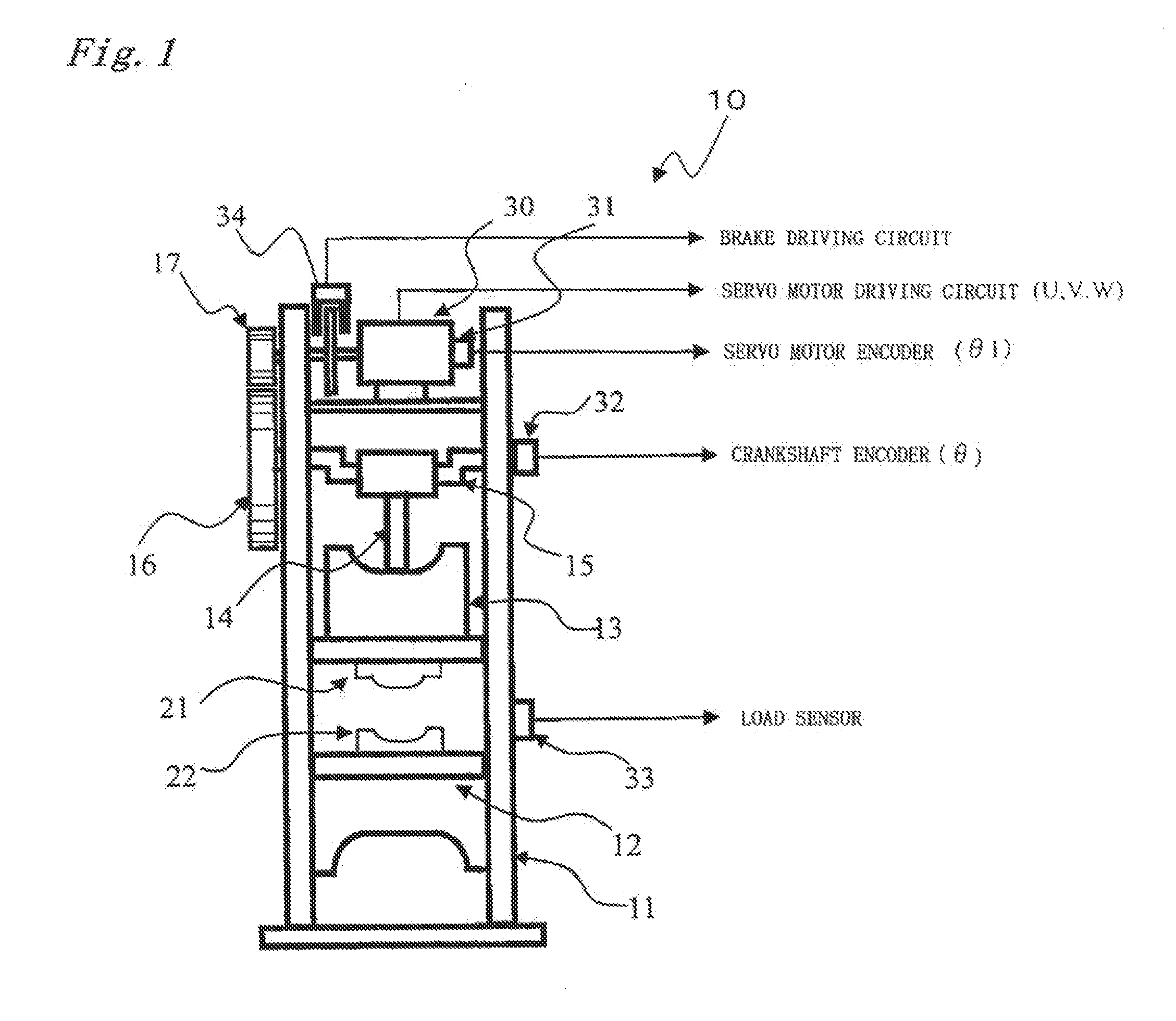
Image

Examples
operation example 1
[0102]An operation example 1 of the electric servo press according to the present invention is described.
[0103]FIG. 7 illustrates a motion setting screen of a display provided to the operating section 43. In an upper part of the screen, an area for setting a designated pressure force Fm and a pressurization limit position is provided. The designated pressure force Fm is a maximum load in the processing. Specifically, a pressure force which reliably enables molding into a final shape is set as the designated pre s sure force Fm. As the pressurization limit position, the position at which the slide cannot be lowered any more in view of the structure of the dies is set. By properly setting the pressurization limit position, the dies can be prevented from being broken due to an erroneous operation or the like.
[0104]In the table on the motion setting screen illustrated in FIG. 7, data relating to the motion of the slide for each step is further set. On the screen, the data can be set for...
operation example 2
[0134]An operation example 2 according to the present invention is described referring to FIGS. 9 and 10.
[0135]The operation example 2 is an example where the pressure-force determination device 60 is more positively used. FIG. 9 illustrates an example of setting performed on the motion setting screen, and FIG. 10 illustrates the operation of the slide 13 according to the setting.
[0136]The activation is performed by pressing the start button of the electric servo press 10 as in the case of the operation example 1. The servo motor drive controller 50 starts driving the servo motor 30 under the positional control so as to drive and lower the slide 13 from the standby position PS at the speed [V1]. The speed [V1] is set high as in the case of the operation example 1 so that the time required for one processing stroke is reduced to improve the productivity.
[0137]In FIG. 9, [method] and [value] of [step shift] in Step 1 are set to [F] and [10%]. Therefore, the step shift is performed by ...
PUM
 Abstract
Description
Claims
Application Information