Method and device for controlling the pressure and/or flow rate of fluid

a technology of fluid flow and flow rate, which is applied in the direction of fluid pressure control, gas/liquid distribution and storage, air-treatment apparatus arrangement, etc., can solve the problems of energy supply, less accurate operation of mechanical control units, and large volume of fluids, and achieve accurate control of the flow rate or the pressure of fluids.

Active Publication Date: 2011-06-09
BE AEROSPACE SYST
View PDF34 Cites 2 Cited by
  • Summary
  • Abstract
  • Description
  • Claims
  • Application Information

AI Technical Summary

Benefits of technology

[0008]Advantageously, a very accurate control may be achieved, since electrical energy is used for the control. A further advantage lies in the possibility of realizing the method in a compact manner with regard to apparatus technology and with a very low weight, since one may make do without an external energy supply and no purely mechanical control of the flow rate and / or of the pressure needs to be effected. Simultaneously, a method which is extremely fail-safe is achieved without an external energy supply, since it may be carried out independently of other supply systems with regard to the energy.
[0012]The device according to an embodiment of the invention for the control of the flow rate and / or of the pressure of a fluid in a conduit, which in particular is suitable for carrying out the described method, includes at least one electrical generator which is designed for the removal of flow energy from a fluid flow and for its at least partial conversion into electrical energy. Further, the device includes a control mechanism for the control of the flow rate and / or of the pressure of the fluid in the conduit. Thereby, the control mechanism is provided with an electric drive which is fed by the generator. By way of the use of an electrical driven control mechanism, one may effect an extremely accurate control of the flow rate and / or of the pressure. Moreover, no additional energy supply needs to be integrated into the device. Thus the device may be operated in an energetically autarkic manner. As a result, a high fail-safety on operation of the device is given. Moreover, the device may be designed in a weight-saving manner, since neither heavy mechanical components nor additional energy sources need to be integrated into the device. In particular, one may make do without a pressure reducer. The electrical generator may thereby be constructed in a single-stage or multi-stage manner.
[0014]Further preferably, the device according to an embodiment of the invention also includes a manual initiation control for subjecting that conduit to fluid flow, which is envisaged for the removal of flow energy by the generator. A device according to one embodiment of the invention may be manually started in this manner, so that that conduit, at which the generator is provided for the removal of flow energy, is subjected to fluid flow. With this, the control mechanism for operational start-up is provided with energy after a manual actuation of the initiation control, so that the further operation of the control is effected automatically. Additionally or alternatively, a manually activatable shut-off valve is provided in the conduits in an advantageous device according to the invention. At the same time, the at least one control mechanism, preferably a valve opened in the idle position, is designed in a manner such that at the beginning of a fluid throughflow in the conduits, it let at least such a high flow rate of the fluid flow through the conduits, that the generator provides an adequately high electric power for the operation of the control means. In this manner too, a sufficiently high fluid flow is made possible by way of an initial manual actuation, so that the generator may automatically drive the control mechanism.
[0016]In a preferred embodiment, the generator of the device is driven by a rotary vane motor. Further preferably, an electrical controlled control valve represents the at least one control mechanism. Particularly preferably, the device is designed for a fluid conduit leading gaseous oxygen and is part of an emergency oxygen supply in unmanned aircraft. It is indeed for this application of the device according to embodiments of the invention, that the possibility of a weight-saving construction, of a more accurate control of the flow rate or of the pressure of a fluid and the energy-autarkic conversion, has been found to be particularly advantageous.

Problems solved by technology

These two alternatives thereby have the following disadvantages: Mechanical control units, as is known, operate in a less accurate manner.
Moreover, they are typically quite heavy, which is disadvantageous.
Control units with electrical components in contrast, although operating in a significantly more accurate manner, disadvantageously always need an energy supply.

Method used


Image

  • Method and device for controlling the pressure and/or flow rate of fluid
  • Method and device for controlling the pressure and/or flow rate of fluid

Examples


Embodiment Construction

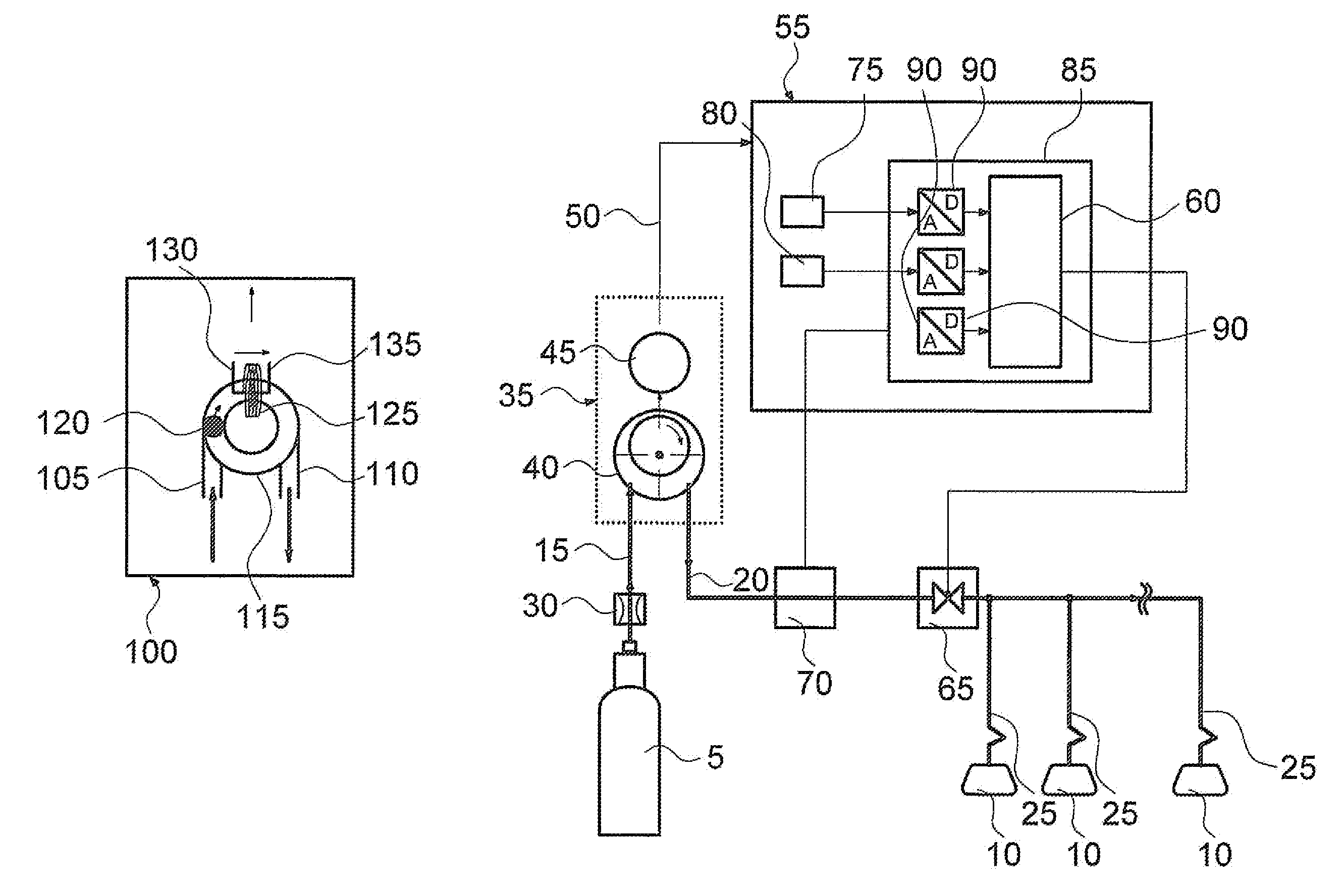
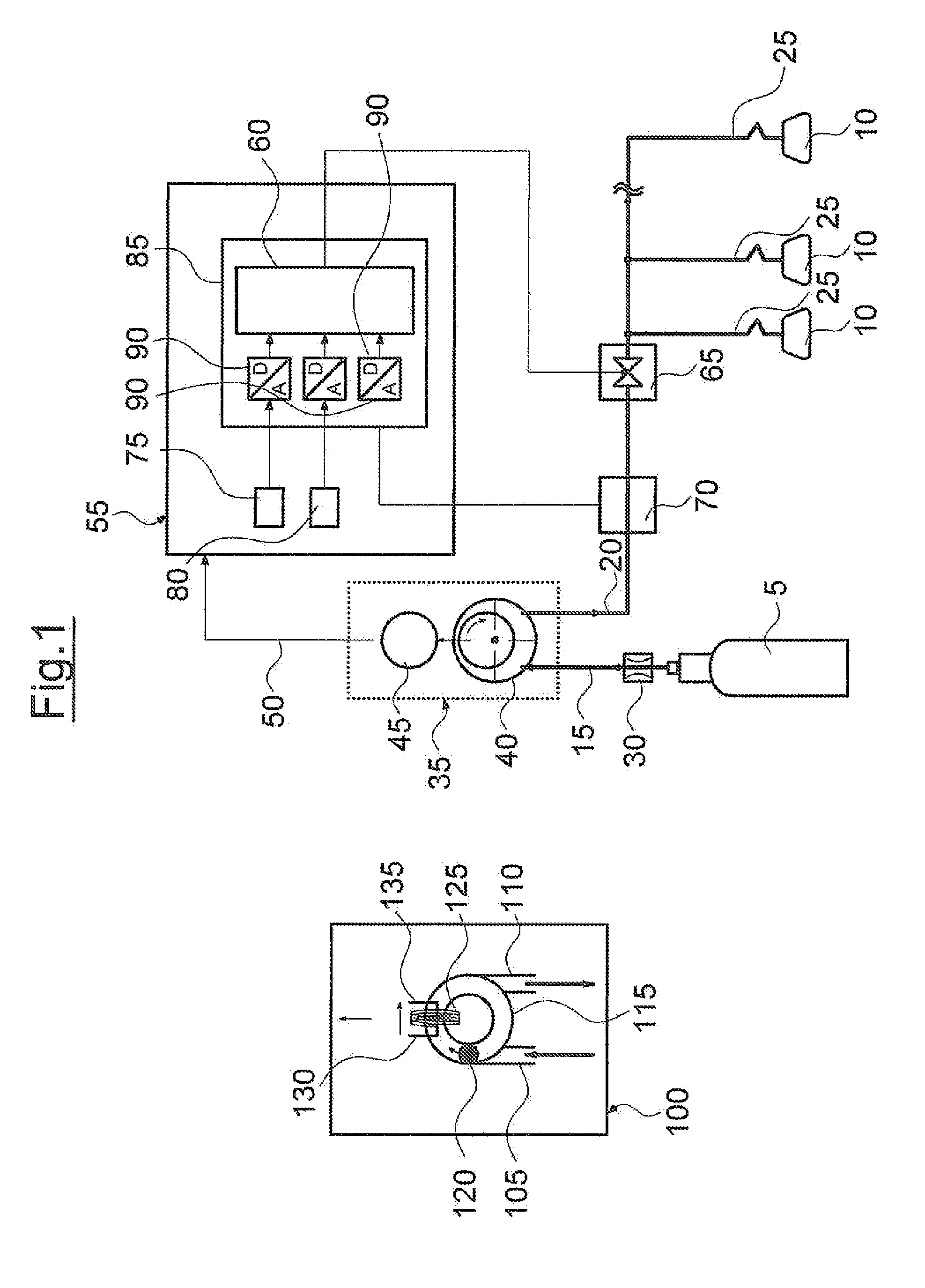
[0020]The invention is hereinafter described by way of example and by way of an illustratory picture. FIG. 1 shows the structure of a device according to the invention for the control of the flow rate of a fluid in a conduit. The shown device for the control of flow rate and / or of the pressure of a fluid in a conduit serves for carrying out the method for the control of the flow rate and / or of the pressure of a fluid. In the embodiment example, gaseous oxygen forms the fluid, and the device is designed for operation in an emergency oxygen supply in manned aircraft.

[0021]Gaseous oxygen in a compressed gas bottle 5 is carried along on board a manned aircraft and is made available to passengers via oxygen masks 10 in an emergency. The oxygen for this reaches the oxygen masks 10 via fluid conduits 15, 20 designed as oxygen conduits, and conduits 25 designed as flexible supply tubes. Since the pressure in the compressed gas bottle 5 may be up to a few 100 bar, the oxygen pressure is redu...


PUM


Abstract

A method for controlling the pressure and / or the flow rate of a fluid includes withdrawing flow energy from a fluid flowing through a pipeline (15). This energy is converted at least partially into electrical energy and used for the electrical control (65) of the flow rate and / or the pressure of a fluid. The device for controlling the flow rate and / or pressure of a fluid in a pipeline (20) has at least one electric generator (35), which is developed for the withdrawal of flow energy from a flowing fluid and for converting this energy at least partially into electrical energy. The device has a control mechanism (65) for controlling the flow rate and / or pressure of a fluid in a pipeline (20) with an electric driving mechanism supplied by the generator (35).

Description

CROSS-REFERENCE TO RELATED APPLICATIONS[0001]This application is a Section 371 of International Application No. PCT / EP2009 / 005528, filed Jul. 30, 2009, which was published in the German language on Feb. 11, 2010, under International Publication No. WO 2010 / 015360 A4 and the disclosure of which is incorporated herein by reference.BACKGROUND OF THE INVENTION[0002]Embodiments of the invention relate to a method for controlling the pressure and / or the flow rate of a fluid, and to a device for controlling the flow rate and / or pressure in a conduit.[0003]It is particularly the case in aircraft, that the task regularly arises, of controlling the flow rate and / or the pressure of a fluid. For example, systems for emergency oxygen supply in aircraft require methods and devices for metering the oxygen.[0004]Basically, there are a multitude of possibilities of controlling the flow rate and / or the pressure of a fluid. These basically fall into two categories: Either the energy necessary for the ...

Claims


Application Information

Patent Timeline
Patent Type & Authority Applications(United States)
IPC IPC(8): B64D13/04F17D1/04F16K31/02
CPCG05D16/2013G05D7/0635Y10T137/0396Y10T137/7761
Inventor CONRAD, RUEDIGERMARZ, HEIKO
Owner BE AEROSPACE SYST
Why Eureka
Try Eureka