Horizontal belt vacuum filter with overhead fluid removal

a technology of vacuum filter and overhead fluid, which is applied in the direction of filtration separation, membrane technology, separation process, etc., can solve the problems of reducing affecting the overall operation of the plant, and affecting the performance of the overall plant operation, so as to reduce the effective prolong the life of the filter media

Inactive Publication Date: 2011-06-09
F L SMIDTH & CO AS
View PDF16 Cites 3 Cited by
  • Summary
  • Abstract
  • Description
  • Claims
  • Application Information

AI Technical Summary

Benefits of technology

[0017]In a horizontal belt filter in accordance with the present invention, the fluid removal member serves to clear, from an upper surface of a slurry layer, an aqueous film that includes suspended particles that can clog the pores in a filter fabric and drastically reduce the effective life of the filter media. In particular, in drying oil sands tailings and separating the solid cake phase from the bitumen and water content, a horizontal belt filter in accordance with the present invention removes an aqueous surface film with suspended dust and bitumen hydrocarbons prior to a raking of the granular materials, thereby obviating a falling of bitumen hydrocarbons and entrained dust into grooves formed by the raking process and into the pores in the filter media. Accordingly, a horizontal belt filter in accordance with the present invention serves to lengthen the life of the filter media and concomitantly the interval between necessary maintenance procedures.

Problems solved by technology

The tailings have poor consolidation and water release characteristics.
These processes may affect the performance of the overall plant operations.
In the treatment of oil sands tailings, raking generally reduces filter media life inasmuch as the filter cloth becomes quickly clogged with bitumen and fine particulate material.

Method used


Image

  • Horizontal belt vacuum filter with overhead fluid removal
  • Horizontal belt vacuum filter with overhead fluid removal
  • Horizontal belt vacuum filter with overhead fluid removal

Examples


Embodiment Construction

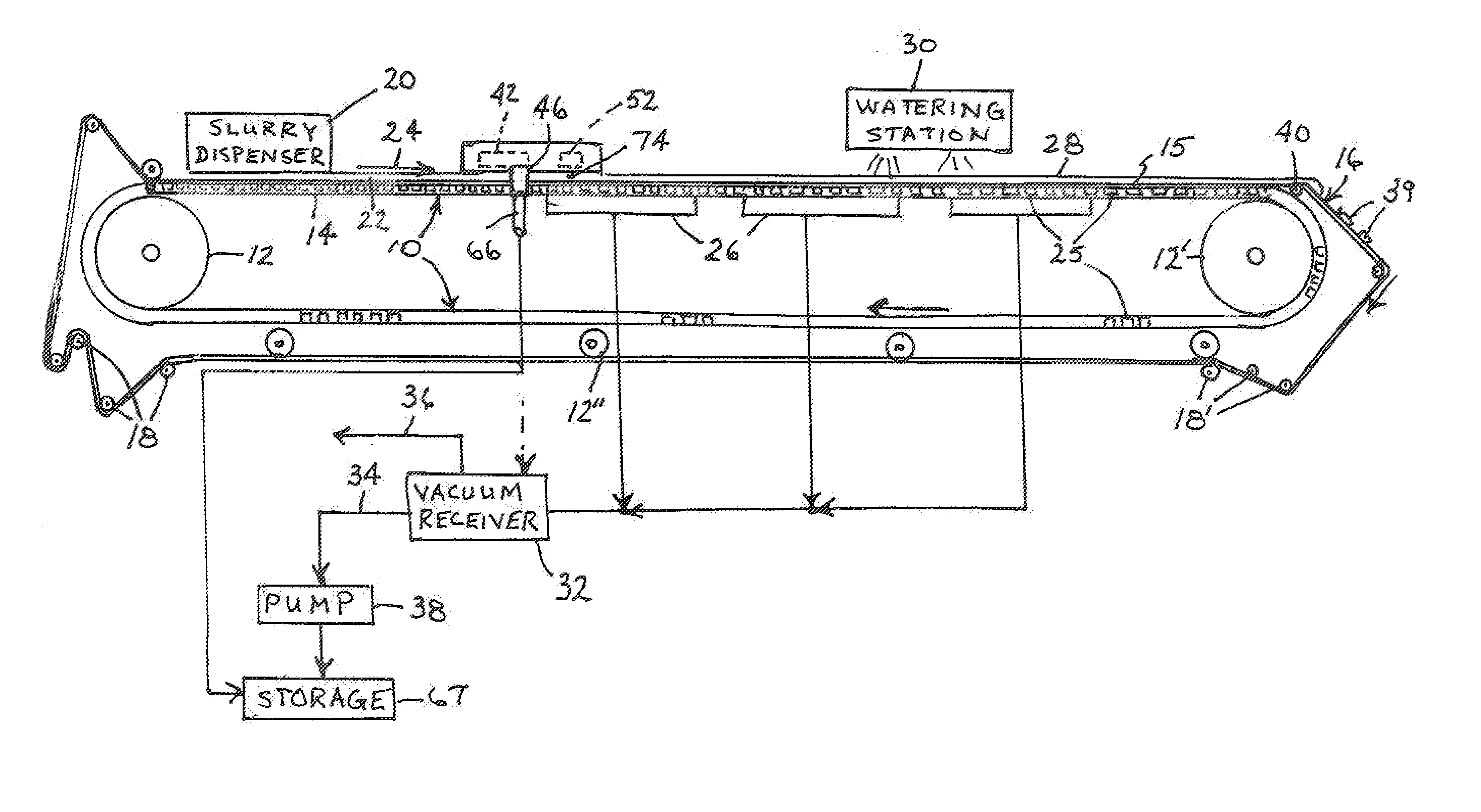
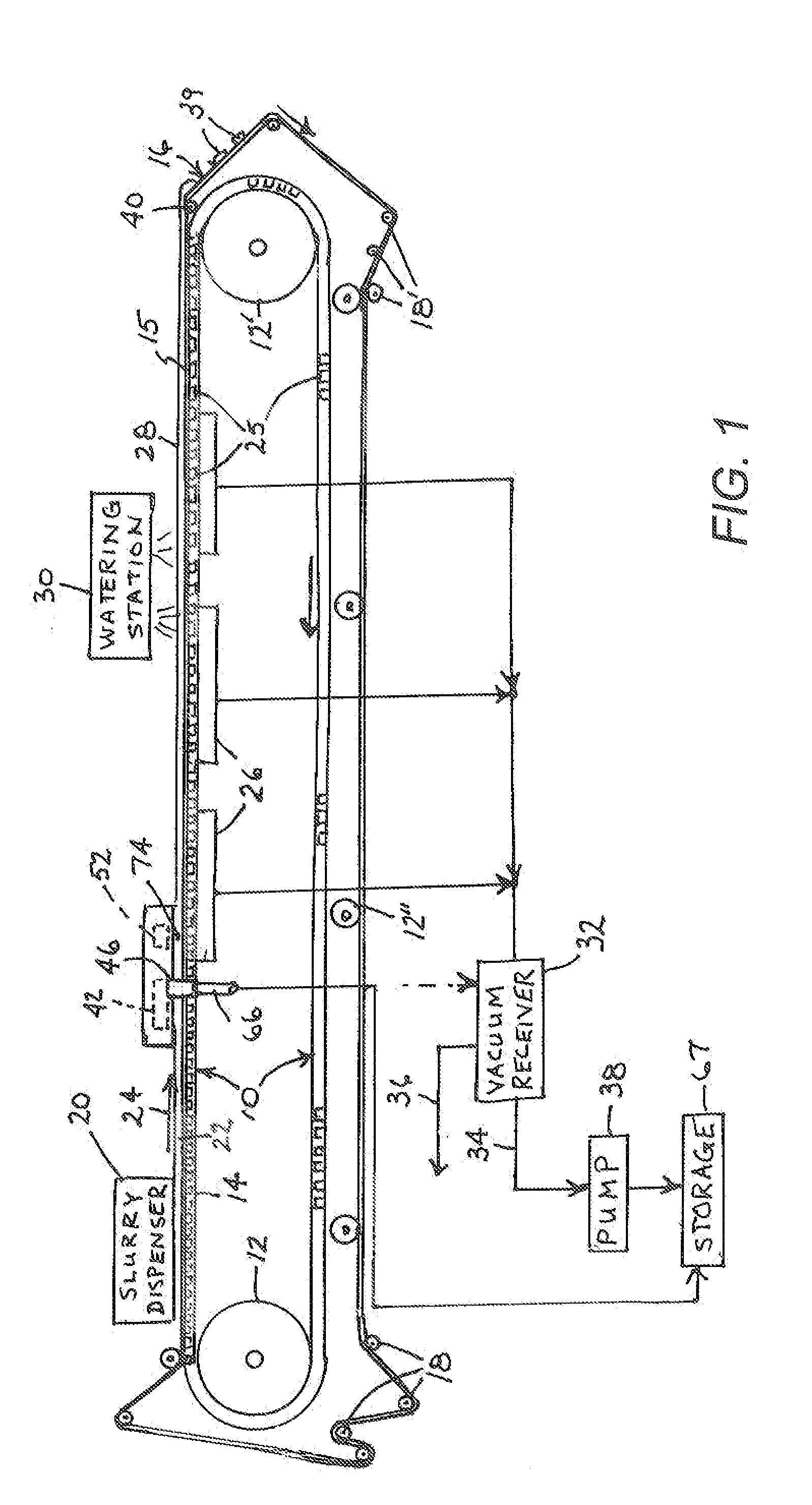
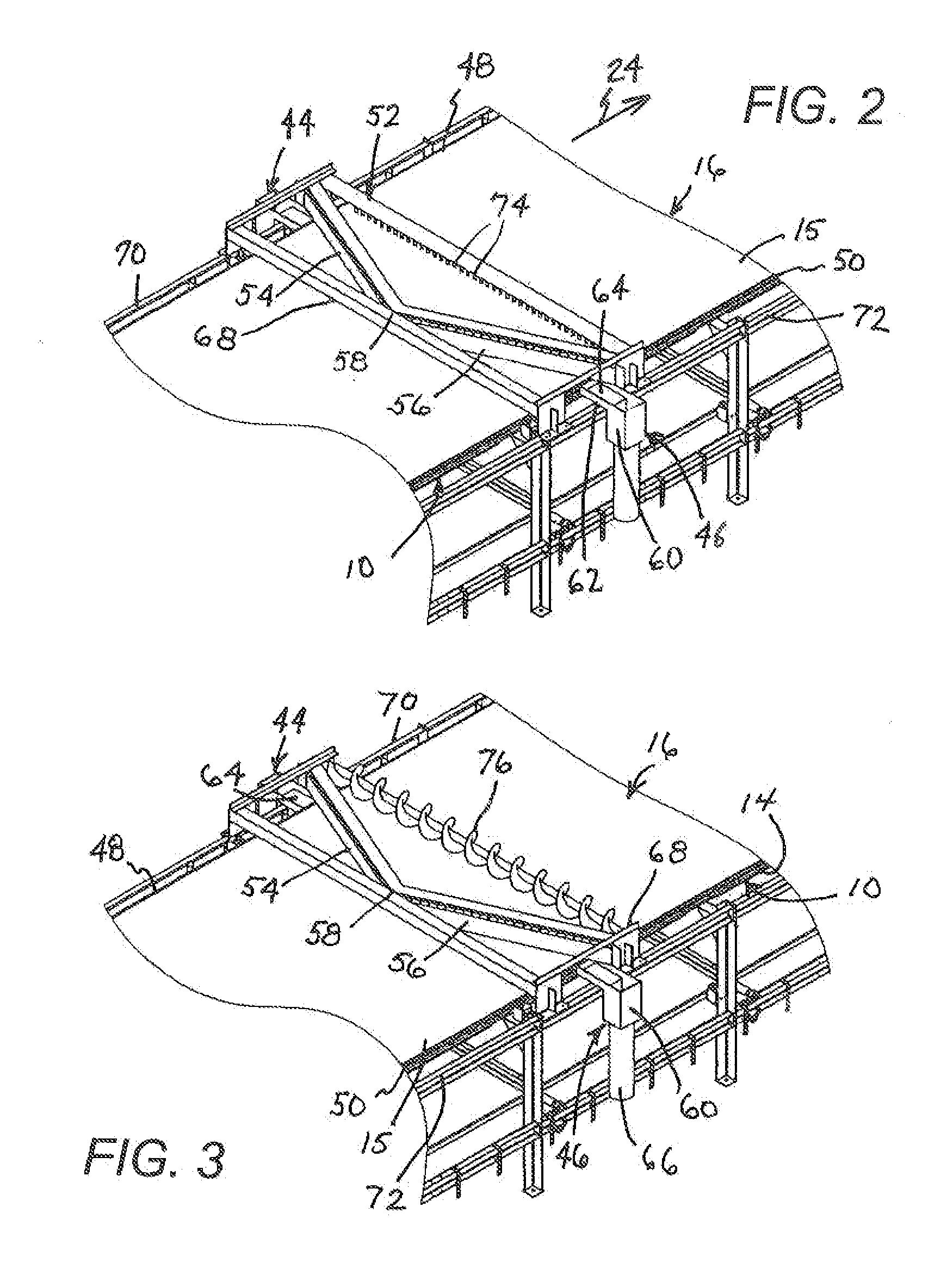
[0021]As depicted in FIG. 1, a horizontal belt vacuum filter comprises a rubber belt 10 supported by rotatable cylinders 12, 12′, 12″ for motion around an endless path. An upper section 14 of belt 10 is disposed in a substantially horizontal plane and supports an upper section 15 of fabric filter web 16 of like width in that horizontal plane. Filter media or web 16 also travels along an endless path and is held by rollers 18, 18′ disposed at spaced locations along the path. A dispenser 20 disposed over an upstream end of belt section 14 deposits a layer of feed slurry 22 such as oil sands tailings uniformly over the full width of filter web 16, in a top feed arrangement. The deposited slurry 22 travels with filter web or media 16, as indicated by a direction of travel arrow 24, and is dried to form a cake 28.

[0022]Belt 10 is provided with transversely oriented channels or grooves 25 that underlie the filter web 16 and is further provided with one or more holes (not shown) in each ch...


PUM

PropertyMeasurementUnit
acute angleaaaaaaaaaa
suctionaaaaaaaaaa
widthaaaaaaaaaa

Abstract

A horizontal belt filter incorporates a filter web, a belt carrying the web in a substantially horizontal plane, at least one fluid removal member disposed above the web upstream of a rake device. The fluid removal member may comprise a channeling dam in conjunction with at least one fluid guide disposed at an end of the dam and adjacent the web and the belt for receiving liquid runoff channeled to the guide by the dam. The fluid removal member may also comprise a suction bar and associated fluid removal means, and a rake member disposed above the web on a downstream side of the fluid removal member. The fluid removal member may include at least two linear or straight bars each disposed at an acute angle relative to a respective edge of the filter web, the linear bars being connected to one another to form a V-shaped composite bar having an apex at an upstream side of the direction of belt travel.

Description

BACKGROUND OF THE INVENTION[0001]This invention relates to horizontal belt vacuum filters. Horizontal belt vacuum filters typically comprise a rubber belt that supports a fabric filter web of like width. The belt and the web are held by rollers and moved along an endless path. The belt is provided with channels that underlie the filter cloth and is further provided with holes that communicate with vacuum boxes or pans disposed beneath the upper stretch of belt and web. A feed slurry is uniformly deposited over the full width of the filter by a top feed arrangement. This eliminates cake formation problems associated with fast settling material. Gravity helps reduce vacuum energy requirements and cake formation time. The cake travels with the filter media and dewatering is accomplished by applying suction from the filter boxes through the holes and channels in the rubber belt and the weave of the filter media. Wash liquid is applied to the cake in one or more independent washing zones...

Claims


Application Information

Patent Timeline
Patent Type & Authority Applications(United States)
IPC IPC(8): B01D33/048B01D33/72B01D33/80
CPCB01D33/04B01D2201/204B01D33/58
Inventor MARSH, ROBERT
Owner F L SMIDTH & CO AS
Why Eureka
Try Eureka