Helicopter landing gear damper

a technology for landing gear and dampers, which is applied in the direction of shock absorbers, mechanical equipment, transportation and packaging, etc., can solve the problems of damper performance adverse effects

Active Publication Date: 2011-06-09
NANOKAS AVIATION L L C
View PDF9 Cites 17 Cited by
  • Summary
  • Abstract
  • Description
  • Claims
  • Application Information

AI Technical Summary

Problems solved by technology

For example, any leakage of nitrogen (a common problem with current systems) causes adverse performance of the damper, such as ground resonance problems.

Method used


Image

  • Helicopter landing gear damper
  • Helicopter landing gear damper
  • Helicopter landing gear damper

Examples


Embodiment Construction

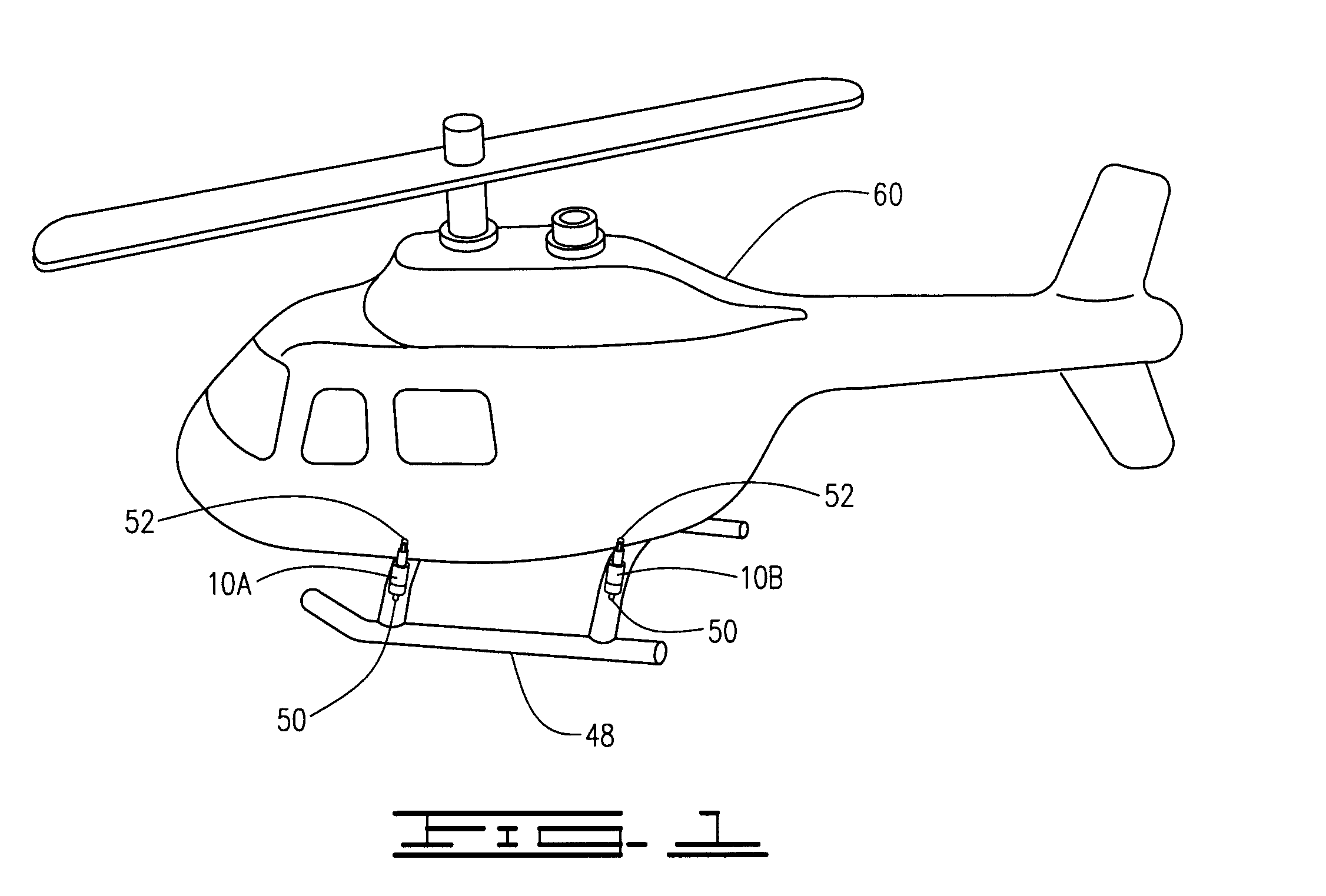
[0020]Referring now to the drawings, and more particularly to FIG. 1, shown therein is a pictorial representation of a helicopter 8 shown equipped with a plurality of helicopter landing gear dampers 10 constructed in accordance with the present invention. As discussed above, the landing gear dampers 10 function to absorb forces during landing operations and to help support the helicopter when on the ground.

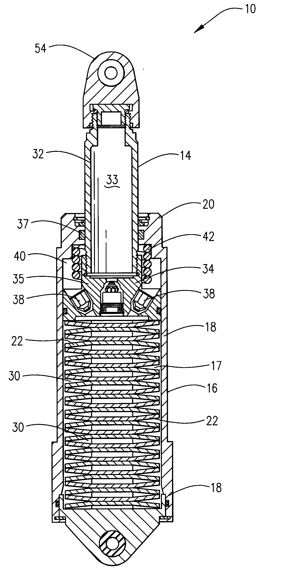
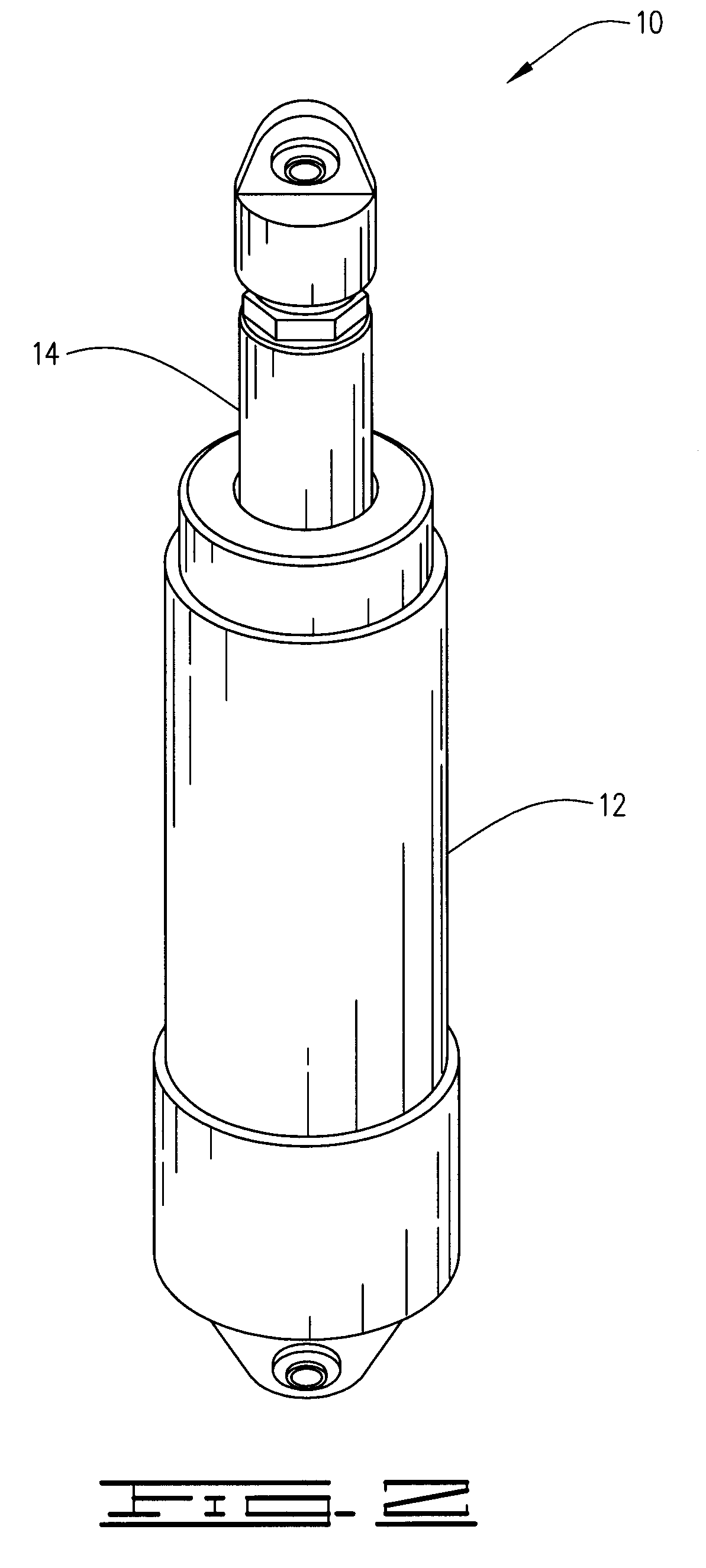
[0021]Referring now to FIGS. 2-3B, the landing gear damper 10 is provided with a barrel 12 and a piston 14. The barrel 12 is provided with a hollow shaft 16 which defines a first hydraulic cavity 17. The barrel 12 is fabricated from a substantially rigid material having a substantially tubular cross sectional area. Furthermore, the hollow shaft 16 is sealed on a bottom end 18 and has a top end 20 which is adapted to receive and / or retain at least a portion of the piston 14. It will be understood that the hollow shaft 16 may be fabricated with any number of different materials, for...


PUM


Abstract

A damper for a landing gear of a helicopter having a barrel, a piston defining a first hydraulic cavity between the piston and a bottom end of the barrel and a second hydraulic cavity between the piston and a top of the barrel, a stack of disc springs disposed within the first hydraulic cavity in a compressed state between the bottom end of the barrel and the piston. Each of the disc springs having a substantially concave side and an opposing substantially convex side, the disc springs stacked in an alternating pattern such that any two adjacent washers have their like sides positioned adjacent to each other. A spring disposed within the second hydraulic cavity such that the spring is compressed between the compression member and the top of the barrel when the piston is in an extended position. A hydraulic fluid is disposed inside at least a portion of the first hydraulic cavity and at least a portion of the second hydraulic cavity. At least one valve is disposed in the piston so as to establish fluid communication between the first hydraulic cavity and the second hydraulic cavity so as to allow bilateral fluid communication between the first hydraulic cavity and the second hydraulic cavity.

Description

CROSS-REFERENCE TO RELATED APPLICATIONS[0001]This application claims the benefit of U.S. Provisional Application No. 61 / 183,127, filed Jun. 2, 2009, which is hereby incorporated herein in its entirety.BACKGROUND OF THE INVENTION[0002]1. Field of the Invention[0003]The present invention relates in general to a landing gear damper and, more particularly, but not by way of limitation, to a landing gear damper for a helicopter which allows for appropriate ground resonance performance.[0004]2. Brief Description of Related Art[0005]Aircraft landing gears, such as landing gears for airplanes, helicopters, and other aircraft are typically equipped with hydraulic damper systems and struts to absorb forces during aircraft landing and to help support the aircraft while on the ground. Helicopter landing gears absorb the energy from landings through damper motion and elastic deformation of struts.[0006]Helicopter landing gears have unique design requirements. Military helicopter landing gears ar...

Claims


Application Information

Patent Timeline
Patent Type & Authority Applications(United States)
IPC IPC(8): B64C25/60F16F13/00
CPCB64C25/52F16F3/02F16F1/32B64C2025/325
Inventor DUNN, MARCUS L.
Owner NANOKAS AVIATION L L C
Why Eureka
Try Eureka