Motor control device, motor drive system and inverter control device

a technology of motor control device and control device, which is applied in the direction of electronic commutator, dynamo-electric gear control, dynamo-electric converter control, etc., can solve the problems of reducing the width of the pwm signal, difficulty in phase current detection of the maximum voltage phase, and increasing the cost of the entire system of the motor

Inactive Publication Date: 2011-06-09
SANYO ELECTRIC CO LTD
View PDF10 Cites 42 Cited by
  • Summary
  • Abstract
  • Description
  • Claims
  • Application Information

AI Technical Summary

Benefits of technology

[0016]A motor control device according to the present invention includes a phase current detection unit which is connected to a current sensor. The current sensor detects current flowing between an inverter which drives a three-phase motor and a DC power supply. The phase current detection unit detects phase currents flowing in three-phase armature windings of the motor from a result of detection by the current sensor, so that the motor control device controls the motor via the inverter on the basis of a result of detection by the phase current detection unit. The phase current detection unit includes an estimation block which estimates phase current of an intermediate voltage phase or current corresponding to the phase current of the intermediate voltage phase as a first estimated current, and the phase current detection unit estimates phase current of a maximum voltage phase or phase current of a minimum voltage phase using the first estimated current so that each phase current can be detected.

Problems solved by technology

Two current sensors (such as current transformers) are usually used for detecting two phase currents, but the use of two current sensors causes cost increase of the entire system in which the motor is incorporated.
However, when the voltage level of the maximum voltage phase becomes close to the voltage level of an intermediate voltage phase, a difference between a pulse width of a PWM signal of the maximum voltage phase and a pulse width of a PWM signal of the intermediate voltage phase decreases so that the phase current detection of the maximum voltage phase becomes difficult.
Similarly, when the voltage level of the intermediate voltage phase becomes close to the voltage level of the minimum voltage phase, a difference between the pulse width of the PWM signal of the intermediate voltage phase and the pulse width of the PWM signal of the minimum voltage phase decreases so that the phase current detection of the minimum voltage phase becomes difficult.
Therefore, noise and vibration of the apparatus incorporating the motor drive system are apt to increase.
The above-mentioned method accompanying correction of the specified voltage value causes a disadvantage also when the overmodulation PWM is used.
Therefore, what is required is a technique to support a period while the phase current of two phases cannot be detected, without correcting the specified voltage value (pulse width).
In addition, it is necessary to use an algorism of the single shunt current detection method, an algorism of utilizing estimated values of three phase currents, and a process of selectively using a detected current value obtained by the former algorism or an estimated current value obtained by the latter algorism, so that a configuration or a program becomes complicated.
Although the conventional problem concerning the motor drive system is described above, the same problem also exists in an inverter control device that is used in a system interconnecting system or the like.

Method used


Image

  • Motor control device, motor drive system and inverter control device
  • Motor control device, motor drive system and inverter control device
  • Motor control device, motor drive system and inverter control device

Examples


first embodiment

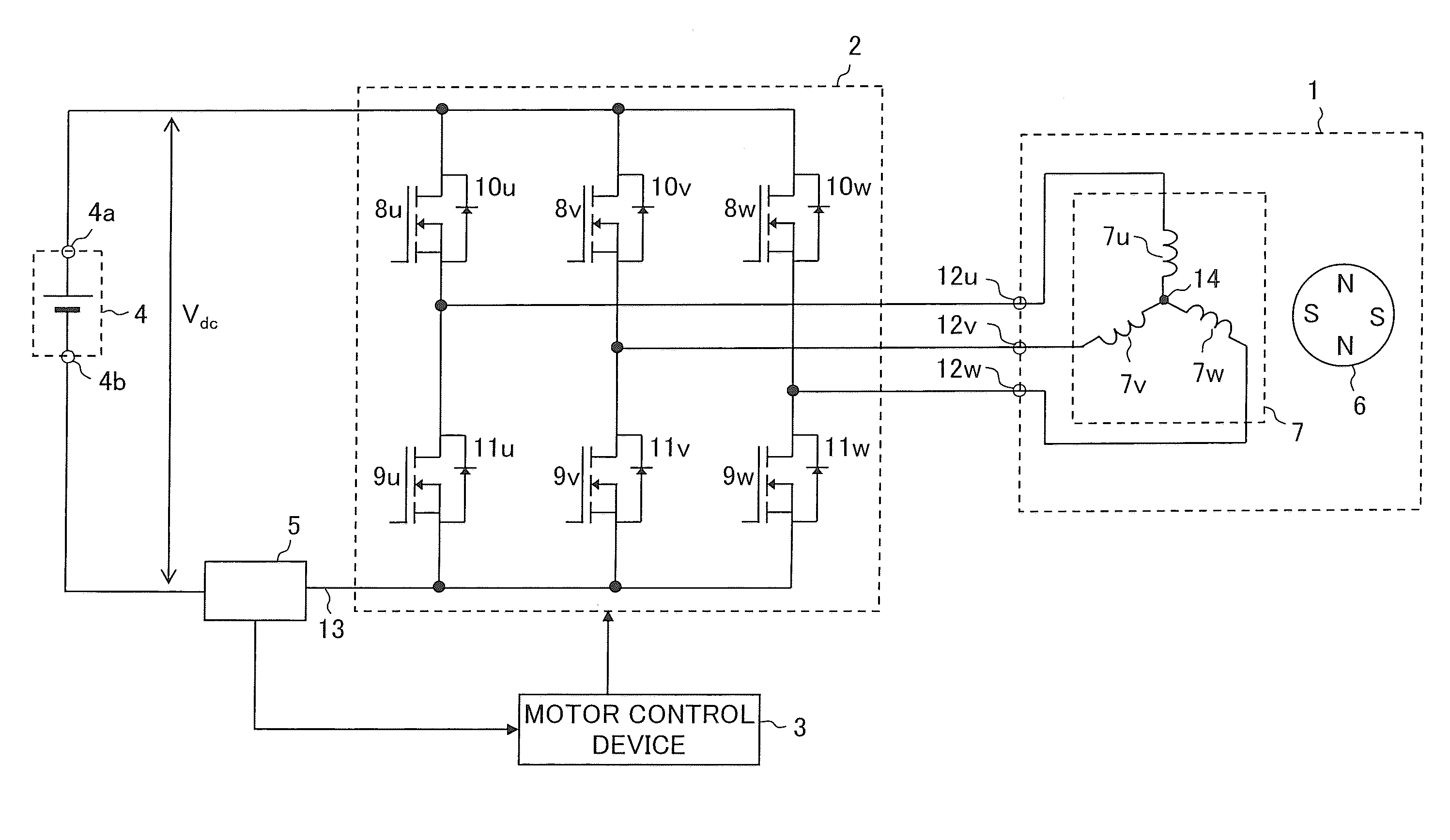
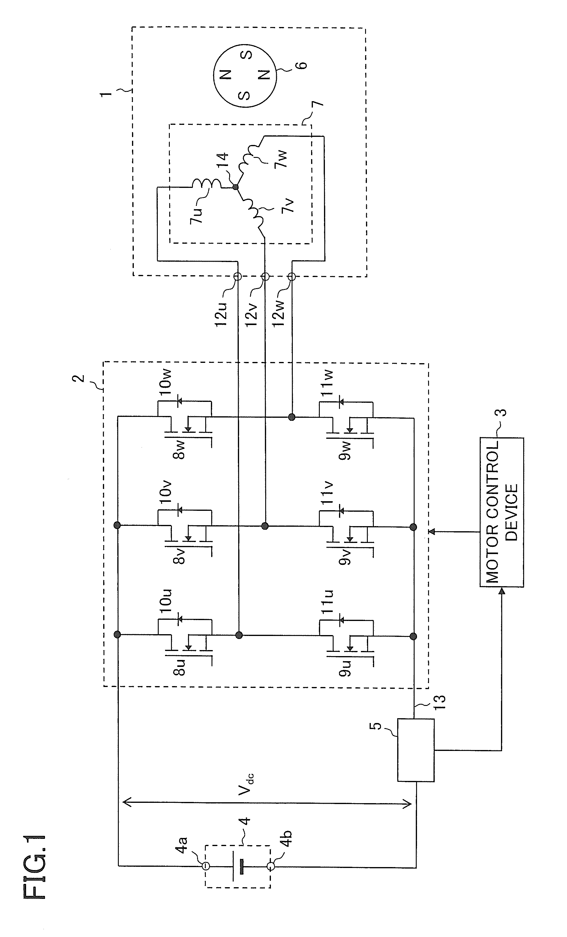
[0051]A first embodiment of the present invention is described. FIG. 1 is a block diagram of a motor drive system according to the first embodiment of the present invention. The motor drive system illustrated in FIG. 1 includes a three-phase permanent-magnet synchronous motor 1 (hereinafter simply referred to as “motor 1”), a pulse width modulation (PWM) inverter 2 (hereinafter simply referred to as “inverter 2”), a motor control device 3, a DC power supply 4, and a current sensor 5. The DC power supply 4 outputs a DC voltage between a positive output terminal 4a and a negative output terminal 4b, where the negative output terminal 4b is a low voltage side. The DC voltage output from the DC power supply 4 and a voltage value thereof are denoted by Vdc.

[0052]The motor control device 3 controls the inverter 2 so as to control the motor 1. Therefore, the motor control device 3 can also be called as an inverter control device.

[0053]The motor 1 includes a rotor 6 having a permanent magne...

example 1

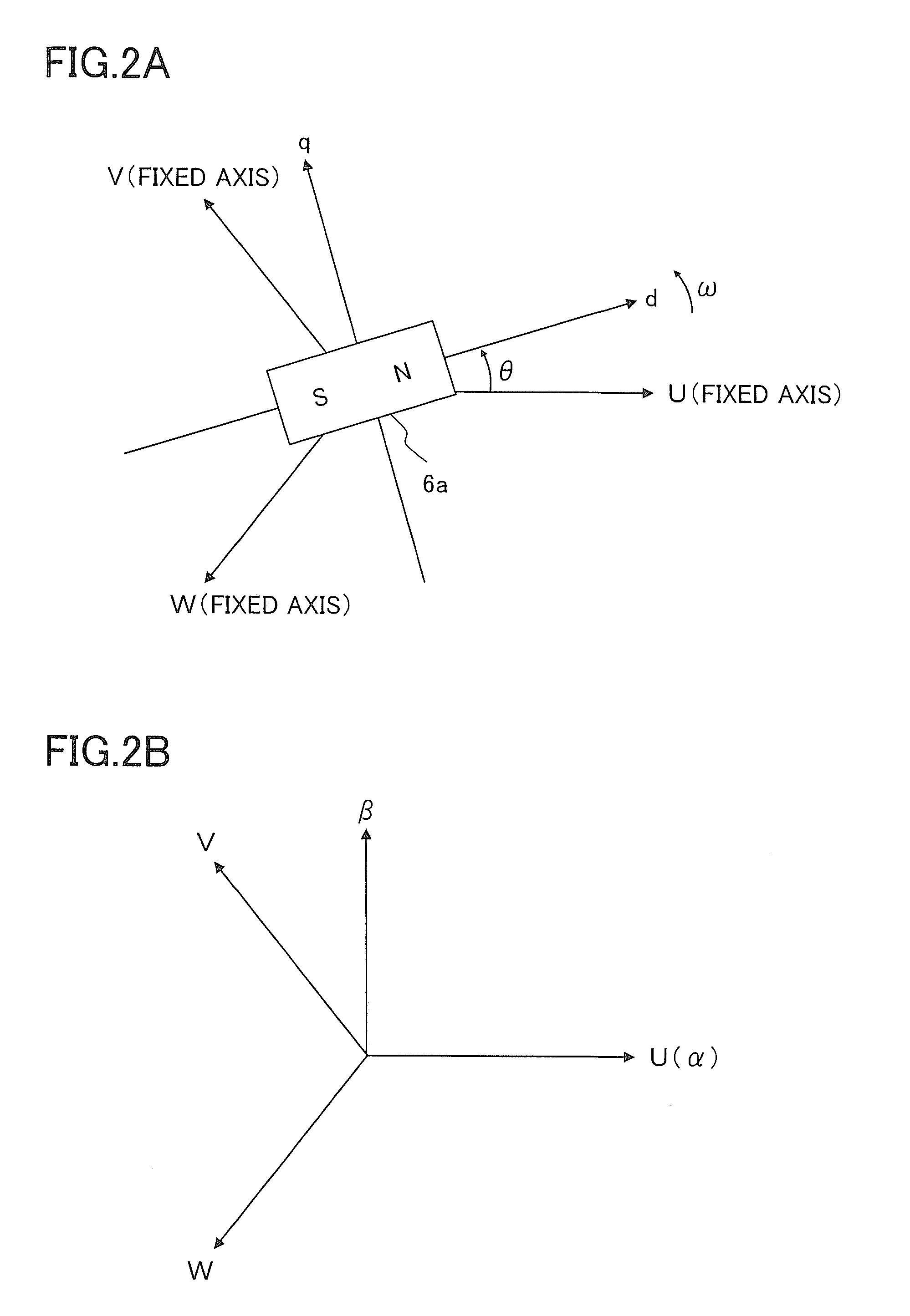
[0116]The determination of the timings ST1 and ST2 and the determination of values of n, SA, and SB are performed on the basis of the specified three-phase voltage values vu*, vv*, and vw* m the fundamental structure, but these determinations may be in performed on the basis of vd*, vq*, and θ instead of vu, vv*, and vw*, or these determinations may be performed on the basis of vα* and vβ* instead of vu, vv*, and vw*. When vd* and vq*, or vα* and vβ* are used for determining the value of n, (θ+ε+π / 6) should be divided by π / 3 so as to determine a quotient, and the quotient should be set to n.

[0117]Here, vα* works as a target value of the α-axis voltage vα to be followed by the α-axis voltage value vα, and vβ* works as a target value of the β-axis voltage vβ to be followed by the β-axis voltage value vβ. The specified voltage values vd* and vq* on the dq-axis are converted into specified voltage values on the αβ-axis on the basis of the rotor position θ so that vα* and vβ* are derived...

example 2

[0118]Example 2 will be described. The specified current values id* and iq* on the dq-axis are used for estimating the phase current imid of the intermediate phase in the fundamental structure. In contrast, id and iq that are to be said as detected current value on the dq-axis (or detected current values on the dq coordinate system) may be used instead of id* and iq* so as to estimate imid. In this case, the phase current detection unit 20 illustrated in FIG. 8 is deformed to be a phase current detection unit 20a illustrated in FIG. 12. The phase current detection unit 20a can be used as the phase current detection unit 20 illustrated in FIG. 7. The phase current detection unit 20a is supplied with id and iq from the coordinate converter 21 instead of id* and iq*. The phase current detection unit 20a includes the blocks 41, 42, and 44, and an intermediate phase current estimation block 43a.

[0119]The estimation block 43a is supplied with the current values id and iq, the rotor posit...


PUM


Abstract

An inverter control device includes a phase current detection unit which is connected to a current sensor. The current sensor detects current flowing between a three-phase inverter which converts a DC voltage into AC three-phase voltages and a DC power supply which outputs the DC voltage, and the phase current detection unit detects phase current flowing in each phase of the inverter from a result of detection by the current sensor, so as to control the inverter on the basis of a result of detection by the phase current detection unit. The phase current detection unit includes an estimation block which estimates phase current of an intermediate voltage phase or current corresponding to the phase current of the intermediate voltage phase as a first estimated current, and estimates phase current of a maximum voltage phase or phase current of a minimum voltage phase using the first estimated current so that each phase current can be detected.

Description

[0001]This nonprovisional application claims priority under 35 U.S.C. §119(a) on Patent Application No. 2009-279386 filed in Japan on Dec. 9, 2009, the entire contents of which are hereby incorporated by reference.BACKGROUND OF THE INVENTION[0002]1. Field of the Invention[0003]The present invention relates to a motor control device which controls a motor and a motor drive system including the same. In addition, the present invention relates to an inverter control device which controls an inverter.[0004]2. Description of Related Art[0005]In order to supply three-phase AC power to a motor for vector control of the motor, it is necessary to detect two phase currents (e.g., U-phase current and V-phase current) among three phase currents, which are U-phase current, V-phase current, and W-phase current. Two current sensors (such as current transformers) are usually used for detecting two phase currents, but the use of two current sensors causes cost increase of the entire system in which ...

Claims


Application Information

Patent Timeline
Patent Type & Authority Applications(United States)
IPC IPC(8): H02P6/18H02P6/16H02P6/06H02P6/08H02P6/17H02P6/28H02P21/00H02P21/14H02P21/18H02P21/22H02P21/24H02P23/14H02P23/16H02P27/04H02P27/08
CPCG01R19/0092H02P27/08H02P21/0035H02M7/5395H02P21/22H02M1/0009H02M7/53876
Inventor TOMIGASHI, YOSHIO
Owner SANYO ELECTRIC CO LTD
Why Eureka
Try Eureka