Display device and method of controlling display device

a display device and display device technology, applied in the field of display devices and a control method of display devices, can solve the problems of increasing manufacturing costs, increasing power consumption, and reducing power performance, and achieve the effects of ensuring display reliability, reducing visibility, and reducing the amount of image information

Active Publication Date: 2011-06-09
SONY CORP
View PDF6 Cites 76 Cited by
  • Summary
  • Abstract
  • Description
  • Claims
  • Application Information

AI Technical Summary

Benefits of technology

[0009]Thus, it is desirable to provide a novel and improved display device and method of controlling a display device capable of ensuring reliability of display at the time of curving of a flexible display device by performing a display control according to a curve amount at the time of curving.
[0014]When the substrate is bending, the control unit may control a split of the image displayed in the display unit in a moderate manner compared to when the substrate is recovering.
[0015]When the curve is such that a display surface of the display unit is a convex portion in a result of detection of the curved state by the displacement sensor, the control unit may control a split of the image displayed in the display unit in a moderate manner compared to when the curve is such that the display surface of the display unit is a concave portion.
[0018]According to the embodiments of the present invention described above, it is possible to provide a novel and improved display device and method of controlling a display device capable of ensuring reliability of display at the time of curving by performing a display control according to a curve amount at the time of curving, when an image in the flexible display device is bent to cause a decrease in visibility and a decrease in the amount of image information provided to the user side.

Problems solved by technology

However, the technique described in Japanese Unexamined Patent Application Publication No. 2005-173193 has a problem in that manufacturing cost increases in order to ensure reliability, since various feedback controls are used, i.e., many algorithms are used, for a complex control combining both a gate signal and a source signal, control of lighting period, and the like.
Also, a complex algorithm control leads to an increase in power consumption of a driver IC, causing a decrease in power performance.
With the technique described in Japanese Unexamined Patent Application Publication No. 2007-240617, detecting a minute refractive index according to deformation is difficult when there is noise due to reflection of external light or light scattering by relatively strong external light from another light source such as, for example, sunlight or fluorescent light in a room.

Method used


Image

  • Display device and method of controlling display device
  • Display device and method of controlling display device
  • Display device and method of controlling display device

Examples


Embodiment Construction

[0037]A preferred embodiment of the present invention will be described in detail below with reference to the accompanying drawings. Note that, in this specification and the drawings, components having substantially the same functional configuration are denoted by the same reference numeral to omit redundant description.

[0038]Note that descriptions will be given in the following order.

[1. Configuration example of display device]

[2. Function block configuration of display device]

[3. Function block configuration of control unit]

[4. Configuration example in which displacement sensor is provided to front and back surfaces]

[5. Another example of lookup table]

[1. Configuration Example of Display Device]

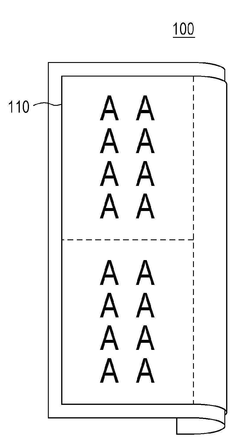
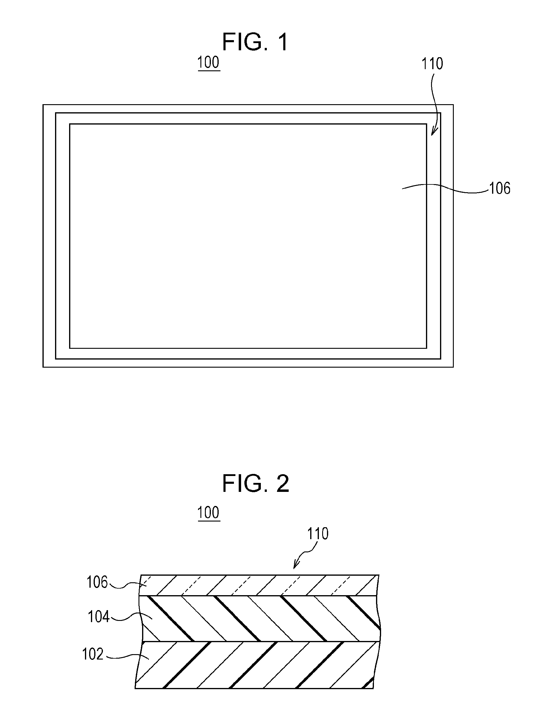
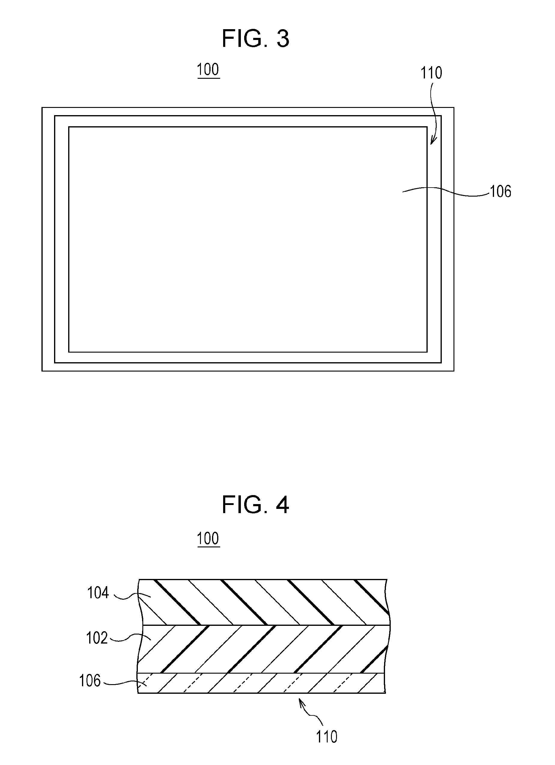
[0039]First, with reference to FIGS. 1 and 2, a schematic configuration of a display device 100 according to an embodiment of the present invention is described. FIG. 1 is a plan view showing a surface on the front side of the display device 100. The display device 100 includes a display un...


PUM


Abstract

A display device includes a flexible substrate, a display unit including multiple light-emitting elements arranged at the substrate and configured to display an image according to an image signal, a displacement sensor provided to at least one of a front surface and a back surface of the substrate and configured to detect a curved state of the substrate, and a control unit configured to execute a control by which the image is split and displayed in the display unit when a curve of the substrate is detected by the displacement sensor.

Description

BACKGROUND OF THE INVENTION[0001]1. Field of the Invention[0002]The present invention relates to a display device and a method of controlling a display device.[0003]2. Description of the Related Art[0004]In recent years, ensuring reliability of a display element in a display device has become an extremely important challenge. Particularly, ensuring structural and mechanical reliability or reliability relating to display performance is still a crucial matter as has been in the past.[0005]For example, Japanese Unexamined Patent Application Publication No. 2005-173193 discloses a technique in which a situation of an image is determined from data, such as image data, that can indicate a display state of a device and lighting of a horizontal scan line is controlled to prevent overcurrent, in order to prevent life degradation of an element due to temperature rise according to current flow amount.[0006]Also, Japanese Unexamined Patent Application Publication No. 2007-240617 describes that ...

Claims


Application Information

Patent Timeline
Patent Type & Authority Applications(United States)
IPC IPC(8): G09G5/00
CPCG09G3/22G09G3/3208G09G2300/0426G09G2340/0464G06F2203/04102G09G2380/02G06F1/1652G06F3/03Y10S345/903G09G3/035
Inventor MORIWAKI, TOSHIKI
Owner SONY CORP
Why Eureka
Try Eureka