
Exposure apparatus, liquid immersion member, and device manufacturing method

a technology of liquid immersion and equipment, applied in the direction of photomechanical treatment, printing, instruments, etc., can solve the problems of reducing throughput, increasing cost, and defecting the pattern formed on the wafer

Inactive Publication Date: 2011-06-09
NIKON CORP
View PDF34 Cites 13 Cited by
  • Summary
  • Abstract
  • Description
  • Claims
  • Application Information

AI Technical Summary

Benefits of technology

[0013]According to this apparatus, on the outer side of a liquid immersion space formed in between an optical member and the object, an auxiliary liquid immersion space is formed by a liquid immersion member between the liquid immersion member and the object. Therefore, an air curtain and the like does not have to be used, and a mesh member having a plurality of holes will not have to be used to recover the liquid inside of the liquid immersion space. Further, exposure with high-resolution to the object becomes possible by the liquid immersion exposure.
[0015]According to this apparatus, on the outer side of a liquid immersion space formed in between an optical member and the object, an auxiliary liquid immersion space is formed by a liquid immersion member between the liquid immersion member and the object. Therefore, an air curtain and the like does not have to be used, and a mesh member having a plurality of holes will not have to be used to recover the liquid inside of the liquid immersion space. Further, exposure with high-resolution to the object becomes possible by the liquid immersion exposure.
[0018]According to this member, an air curtain and the like does not have to be used, and a mesh member having a plurality of holes will not have to be used to recover the liquid inside of the liquid immersion space.

Problems solved by technology

Therefore, contaminants adhered to the porous member, which became a cause of defects in the pattern formed on the wafer (hereinafter shortly referred to as a defect).
Accordingly, the contaminated porous member has to be replaced; however, this replacement becomes a cause of increasing the downtime of the apparatus, which leads to a decrease in throughput, which then leads to an increase in cost.
The liquid which has remained on the wafer becomes a cause of defects.
Further, the heat of evaporation which is generated when the remaining liquid evaporates becomes a cause of local deformation of the wafer.
Further, when the liquid immersion space was limited by an air curtain like the one disclosed in U.S. Pat. No. 7,193,681 and the like, a problem such as deformation of the wafer due to the heat of evaporation could occur.
However, the high refractive index liquid generally has a characteristic of having a small contact angle (a large wettability) which makes it difficult to maintain its shape.
Accordingly, it was difficult to keep a high refractive index liquid in a local area between the projection optical system and the substrate, and a local-fill liquid immersion exposure using the high refractive index liquid could not be performed in the past.

Method used


Image

  • Exposure apparatus, liquid immersion member, and device manufacturing method
  • Exposure apparatus, liquid immersion member, and device manufacturing method
  • Exposure apparatus, liquid immersion member, and device manufacturing method

Examples


first embodiment

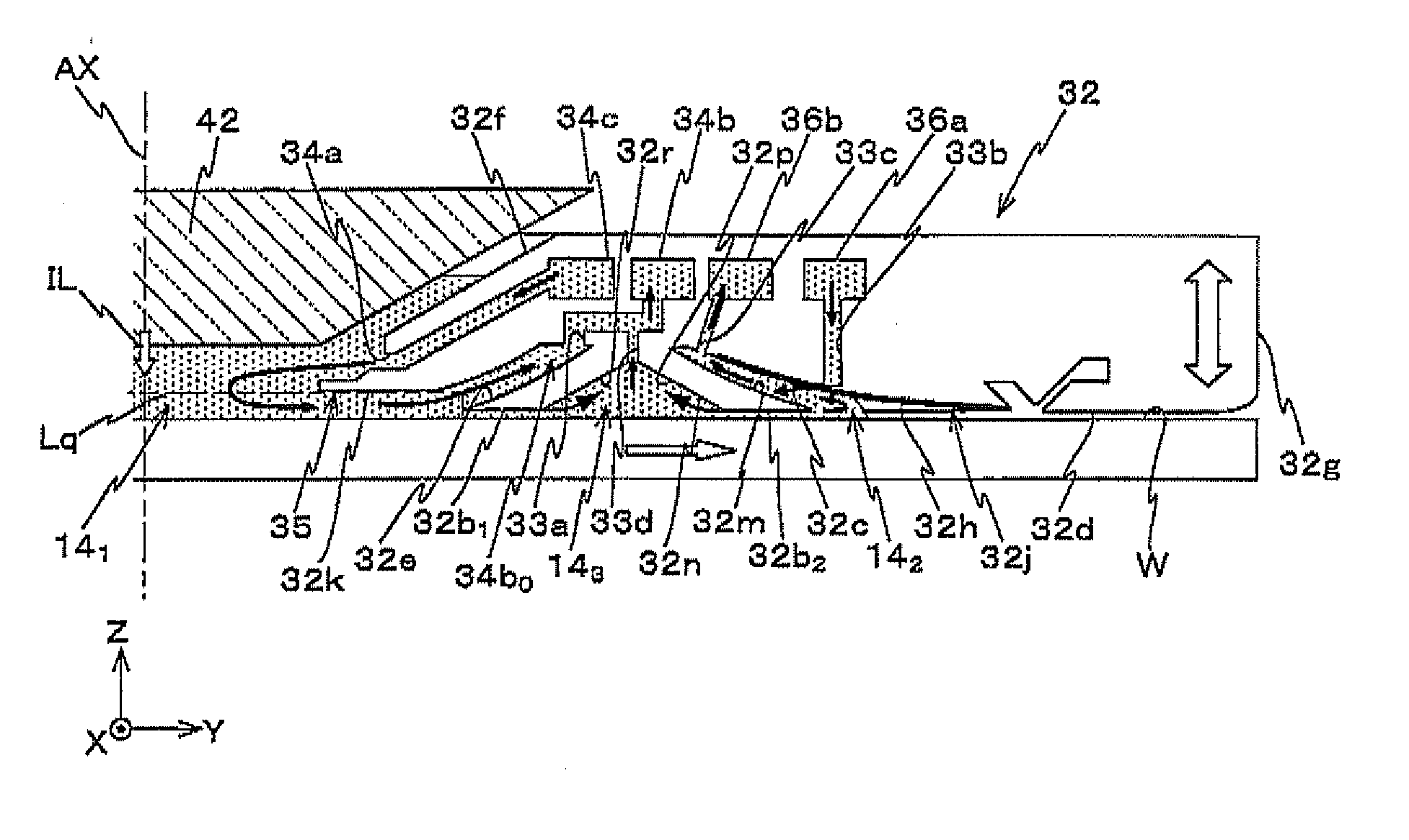
[0041]Hereinafter, a first embodiment of the present invention will be described, with reference to FIGS. 1 to 13.

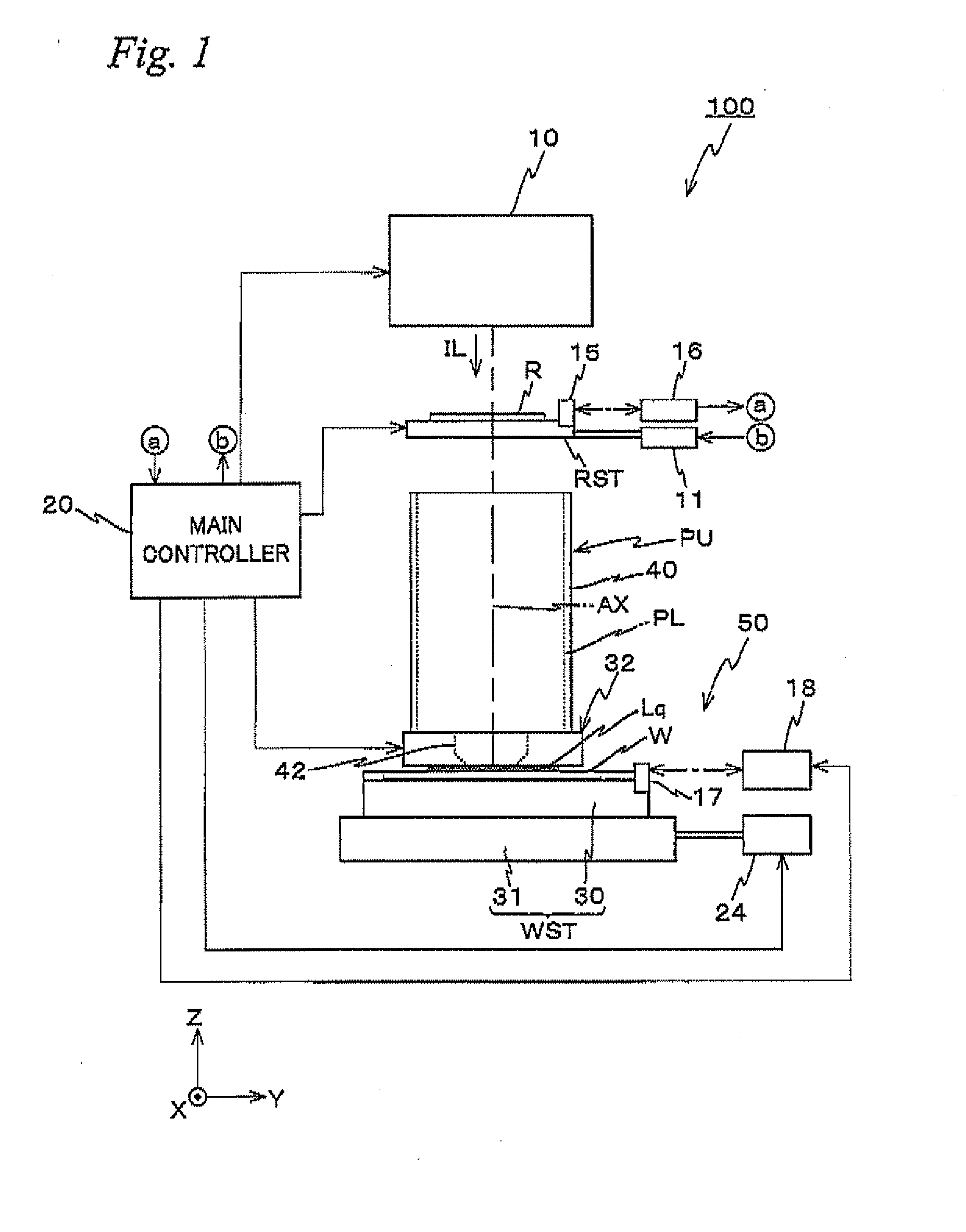
[0042]FIG. 1 schematically shows the configuration of an exposure apparatus 100 related to the present embodiment. Exposure apparatus 100 is a projection exposure apparatus by the step-and-scan method (or a so-called scanning stepper). As it will be described later, a projection optical system PL is arranged in the embodiment, and in the description below, a direction parallel to an optical axis AX of projection optical system PL will be described as the Z-axis direction, a direction within a plane orthogonal to the Z-axis direction in which a reticle and a wafer are relatively scanned will be described as the Y-axis direction, a direction orthogonal to the Z-axis and the Y-axis will be described as the X-axis direction, and rotational (inclination) directions around the X-axis, the Y-axis, and the Z-axis will be described as θx, θt, and θz directions, respectively.

[0043...

second embodiment

[0151]Next, a second embodiment will be described. Herein, the same or similar reference signs are used for the components that are the same as or similar to those in the first embodiment described previously, and the description thereabout is simplified or omitted.

[0152]While the exposure apparatus of the second embodiment partly differs from the first embodiment previously described regarding the configuration of the nozzle member, configuration and the like of other parts are similar to the first previously described.

[0153]In the nozzle member of the second embodiment as well, inclined surface 32c is formed on the inner bottom surface (upper surface) facing wafer W of recess section 32h. However, in nozzle member 32′ related to the second embodiment, as shown in FIG. 14, a plurality of grooves 38a is formed on inclined surface 32c in a radial direction (radiation direction) centering on a central axis (coincides with optical axis AX) parallel to the Z-axis at a predetermined pitc...

third embodiment

[0180]Next, a third embodiment will be described, with reference to FIGS. 19 and 20. Herein, the same or similar reference signs are used for the components that are the same as or similar to those in the first and second embodiments described previously, and the description thereabout is simplified or omitted.

[0181]FIG. 19 shows a longitudinal sectional view of the +Y side half of a nozzle member 32A equipped in an exposure apparatus of the third embodiment, with the −Y side half omitted. The reason why the −Y side half was omitted is because nozzle member 32A has a shape which is rotationally symmetric around an axis (coincides with optical axis AX in the embodiment) parallel to the Z-axis. Further, FIG. 20 is a block diagram that shows an input / output relation of a main controller which is equipped in the exposure apparatus of the third embodiment.

[0182]The exposure apparatus of the third embodiment differs from the exposure apparatus of the first embodiment previously described ...


PUM


Abstract

Liquid is held between a tip lens of a projection optical system and a wafer on a wafer stage, using a nozzle member which has shape enclosing an optical path of an illumination light, and a bottom surface to which wafer W is placed facing via a predetermined clearance that has an annular recess section formed having multiple projecting sections. This prevents adhesion of contamination and liquid from remaining that become factors of defects of a pattern formed on a wafer. The nozzle member preferably has an annular shaped inclined surface whose gap with the wafer surface becomes smaller from the inner side to the outer side, formed on an inner bottom surface facing the wafer of an outer recess section formed on the bottom surface of the nozzle member.

Description

CROSS-REFERENCE TO RELATED APPLICATIONS[0001]This non-provisional application claims the benefit of Provisional Application No. 61 / 282,029 filed Dec. 4, 2009, Provisional Application Nos. 61 / 308,570, 61 / 308,574, and 61 / 308,592 filed Feb. 26, 2010, and Provisional Application No. 61 / 390,716 filed Oct. 7, 2010, the disclosures of which are hereby incorporated herein by reference in their entirety.BACKGROUND OF THE INVENTION[0002]1. Field of the Invention[0003]The present invention relates to exposure apparatuses, liquid immersion members, and device manufacturing methods, and more particularly, to an exposure apparatus used in a photolithography process when producing electronic devices such as a semiconductor device, a liquid crystal display device and the like that performs exposure by a liquid immersion method, a liquid immersion member which can be used to form a liquid immersion space that is filled with liquid, and a device manufacturing method which uses the exposure apparatus....

Claims


Application Information

Patent Timeline
Patent Type & Authority Applications(United States)
IPC IPC(8): G03B27/52
CPCG03F7/70341G03F7/70925G03F7/70858
Inventor SHIBAZAKI, YUICHI
Owner NIKON CORP
Features
  • Generate Ideas
  • Intellectual Property
  • Life Sciences
  • Materials
  • Tech Scout
  • Unparalleled Data Quality
  • Higher Quality Content
  • 60% Fewer Hallucinations
Learn More