
Occlusion method and apparatus

a tubular structure and occlusion technology, applied in the field of occlusion of vessels and other tubular structures, can solve the problems of coils not being repositionable, too large drawbacks, and long vascular segments that are often obliterated

Inactive Publication Date: 2006-02-07
BOARD OF RGT THE UNIV OF TEXAS SYST
View PDF50 Cites 150 Cited by
  • Summary
  • Abstract
  • Description
  • Claims
  • Application Information

AI Technical Summary

Benefits of technology

[0016]In one aspect, the invention is an occluder including a elastically deformable members, and a jacket. As used herein, by “elastically deformable” it is meant that deformation is non-permanent and an original shape may be substantially recovered, or regained, upon the release of a force (which may be mechanical, electromagnetic, or any other type of force). By “substantially recovered”, it is meant that recovery need not be such that the exact original shape may be regained. Rather, it is meant that some degree of plastic deformation may occur. In other words, recovery need not be total. The plurality of elastically deformable members are secured in spaced relation and extend in arcuate conformation therebetween. The plurality of elastically deformable members are operable to become compressed upon application of a force and to recover the arcuate conformation upon removal of the force. The jacket is in operable relation to the plurality of elastically deformable members and is configured to cover at least a portion of the plurality of elastically deformable members.

Problems solved by technology

Although coil type occlusion devices have shown at least a degree of utility, they have a number of drawbacks that could be significant in some applications.
Moreover, a long vascular segment is often obliterated because of the frequent need for multiple coils and the coils often remain elongated within the vessel because their unconstrained diameter is larger than the vascular lumen.
However, since optimal arrangement of the coil alone may not prevent migration in some cases, such as high flow conditions or venous placement, a coil anchoring system has been devised (Konya et al., 1998).
Although an anchoring system may stabilize a coil conglomerate within the vasculature, significantly reducing or eliminating the possibility of coil migration, such a system may render the coil non-repositionable.
Although such non-coil devices may be repositionable, they too exhibit drawbacks.
For instance, the quadruple-disc device is several centimeters long in an elongated fashion, making difficult to keep the superselective position of the catheter tip during deployment.
A common disadvantage of both designs is that they lack guidewire compatibility.
Another relative disadvantage of both devices is their cost of manufacturing.
Because of the size of the delivery sheath, such a device is not suitable for the treatment of patients with a body weight of less than 8 kg.
Using even a larger umbrella, this procedure is not recommended for the treatment of the lesions with a diameter of 8 mm or above (Latson, 1991).
One of the main drawbacks of the Rashkind umbrella is that it is not suitable for occlusion of all types of PDA.
Longer PDA may hinder the discs to be positioned in the proper way, that is, parallel to each other, thereby deteriorating its self-anchoring.
Another disadvantage of the umbrella is that the occluding capacity of the design depends exclusively on the thrombogenicity of the porous Dacron material, frequently resulting in partial and lengthy occlusion.
Formerly, detachable and non detachable balloons were used for this purpose, but they did not cause satisfactory ureteral occlusion.
Migration as well as deflation of the balloons occurred relatively frequently (Gunter, 1984; Papanicolau, 1985) leading to recurrence of the urine leakage.
A silicone ureteral occluder was developed and used with only limited success because of device migration (Sanchez, 1988).
This resulted in repositioning and consequent incomplete ureteral occlusion.
The lack of appropriate self-anchoring results in coil migration which eventually deteriorates the occlusive effect.
Problems pointed out in the foregoing are not intended to be exhaustive but rather are among many that tend to impair the effectiveness of previously known occlusion systems.
Other noteworthy problems may also exist; however, those presented above should be sufficient to demonstrate that previous techniques appearing in the art have not been altogether satisfactory, particularly in providing fast, non-migratory, self-anchoring, repositionable occlusion.

Method used


Image

  • Occlusion method and apparatus
  • Occlusion method and apparatus
  • Occlusion method and apparatus

Examples


examples

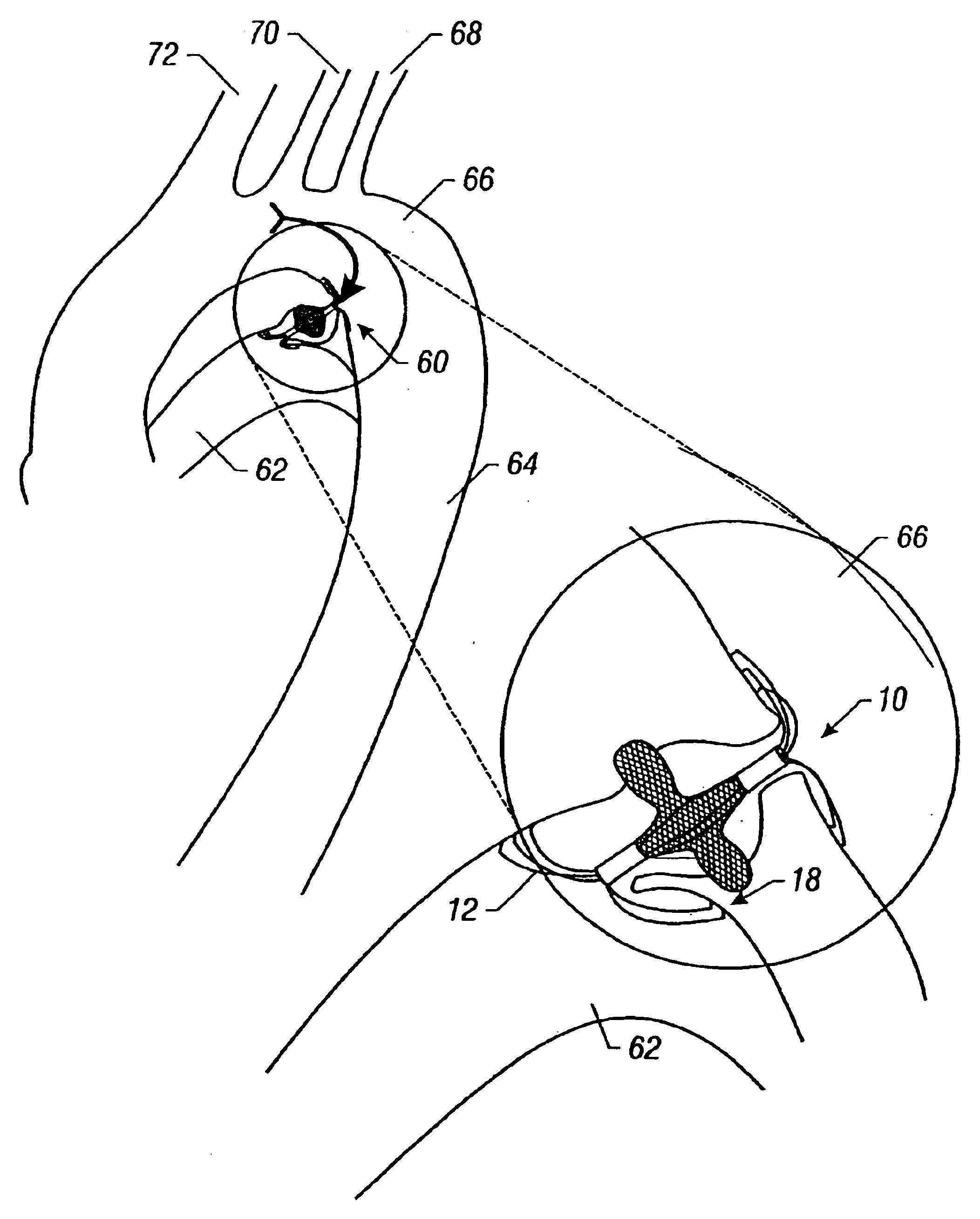
[0100]To achieve quick, limited-size vascular occlusion, a self-expanding, self-anchoring basket-shaped vascular occlusion device has been designed and fabricated. Studies have been performed demonstrating occluders 10 in accordance with the present disclosure in a high-flow arterial model.

Device Construction

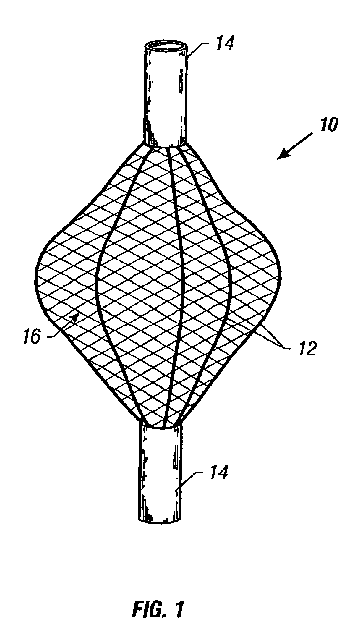
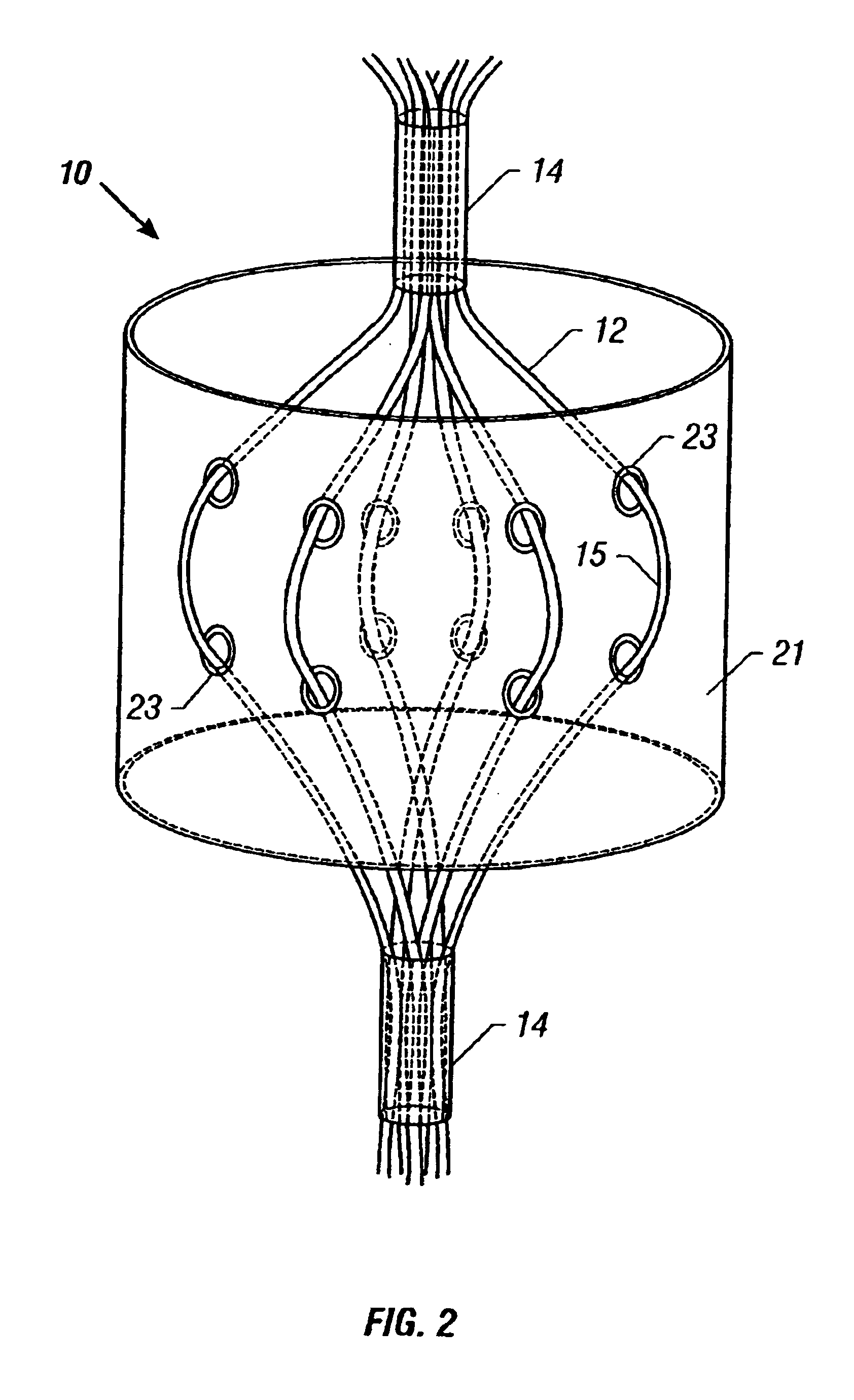
[0101]Devices of varying size have been constructed from four 0.009 inch nitinol wires held together at each end by a stainless steel clip. Nitinol, an alloy composed of 55% nickel and 45% titanium with a titanium-oxide layer, has been used because of its shape memory properties and established biocompatibility (Liu and Stice, 1990; Castleman et al., 1976). The disclosed occluder configuration has been achieved by pushing the two ends of the wire frame toward each other and then heating the device to 500° C. for 120 min. After allowing the device to cool to room temperature, a bead of silver solder was placed around each steel clip for reinforcement.

[0102]An elastic Dacron jacke...


PUM


Abstract

An occlusion method and apparatus. The occluder includes elastically deformable members and a jacket. The elastically deformable members are secured in spaced relation and extend in arcuate conformation therebetween. The jacket covers at least a portion of the elastically deformable members. The elastically deformable members are configured to become compressed upon application of a force and to recover the arcuate conformation upon removal of the fore to occlude a site.

Description

[0001]This application is a divisional application of, and claims priority to, U.S. patent application Ser. No. 09 / 263,382, filed Mar. 5, 1999 and issued as U.S. Pat. No. 6,368,338.BACKGROUND OF THE INVENTION[0002]1. Field of the Invention[0003]The present invention relates generally to the field of occlusion of vessels and other tubular structures in the body. More particularly, it concerns a method and apparatus for repositionable, self-anchoring occlusion including vascular and ureter occlusion.[0004]2. Description of Related Art[0005]Percutaneous occlusion techniques have become indispensable tools in minimally invasive management of a wide range of pathological conditions. Use of permanent mechanical occlusion devices has been shown to be equivalent to that of surgical ligation. The Gianturco-Wallace stainless steel coil (Cook Inc., Bloomington, Ind.) has been the most widely used permanent, expandable intravascular occlusion device for transcatheter delivery (Gianturco et al.,...

Claims


Application Information

Patent Timeline
Patent Type & Authority Patents(United States)
IPC IPC(8): A61M29/00A61B17/12
CPCA61B17/12022A61B17/12099A61B17/12172A61B17/12177A61B17/12109A61B2017/1205A61B17/0057A61B2017/00575A61B2017/00592A61B2017/00601A61B2017/00623A61B2017/00579
Inventor KONYA, ANDRASWALLACE, SIDNEYWRIGHT, KENNETH C.
Owner BOARD OF RGT THE UNIV OF TEXAS SYST
Features
  • Generate Ideas
  • Intellectual Property
  • Life Sciences
  • Materials
  • Tech Scout
  • Unparalleled Data Quality
  • Higher Quality Content
  • 60% Fewer Hallucinations
Learn More