Speaker device

Inactive Publication Date: 2011-06-09
ALPINE ELECTRONICS INC
View PDF5 Cites 9 Cited by
  • Summary
  • Abstract
  • Description
  • Claims
  • Application Information

AI Technical Summary

Benefits of technology

[0046]With such a configuration, the use of an adhesive agent can be suppressed.
[0047]With the speaker device according to the above-described configurations, the magnet, the outer yoke and the inner yoke are assembled in a state wherein the inner yoke and the outer yoke are subjected to positioning by the positioning members so that a magnetic gap is formed, whereby the magnetic circuit can be assembled with good workability with the positionin

Problems solved by technology

However, workability is poor for adhering the parts that make up the magnetic circuit with an adhesive agent while accurately maintaining the relative positional relation so that the narrow magnetic ga

Method used


Image

  • Speaker device
  • Speaker device
  • Speaker device

Examples


first embodiment

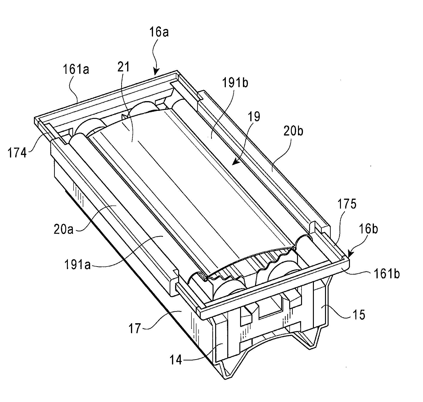
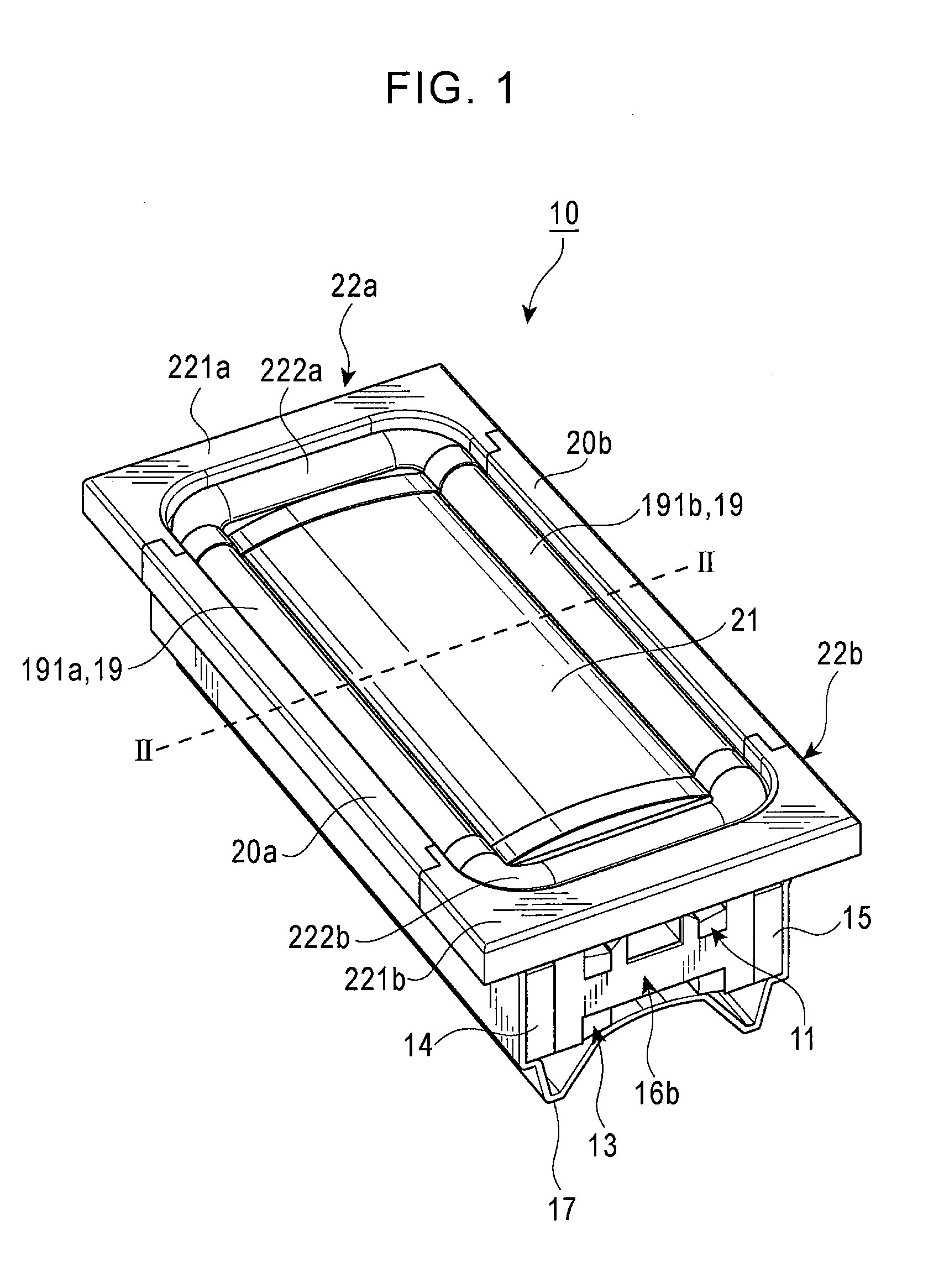
[0093]Embodiments of the present invention will be described below with reference to the appended diagrams. An external view of a speaker device according to the present invention is as shown in FIG. 1.

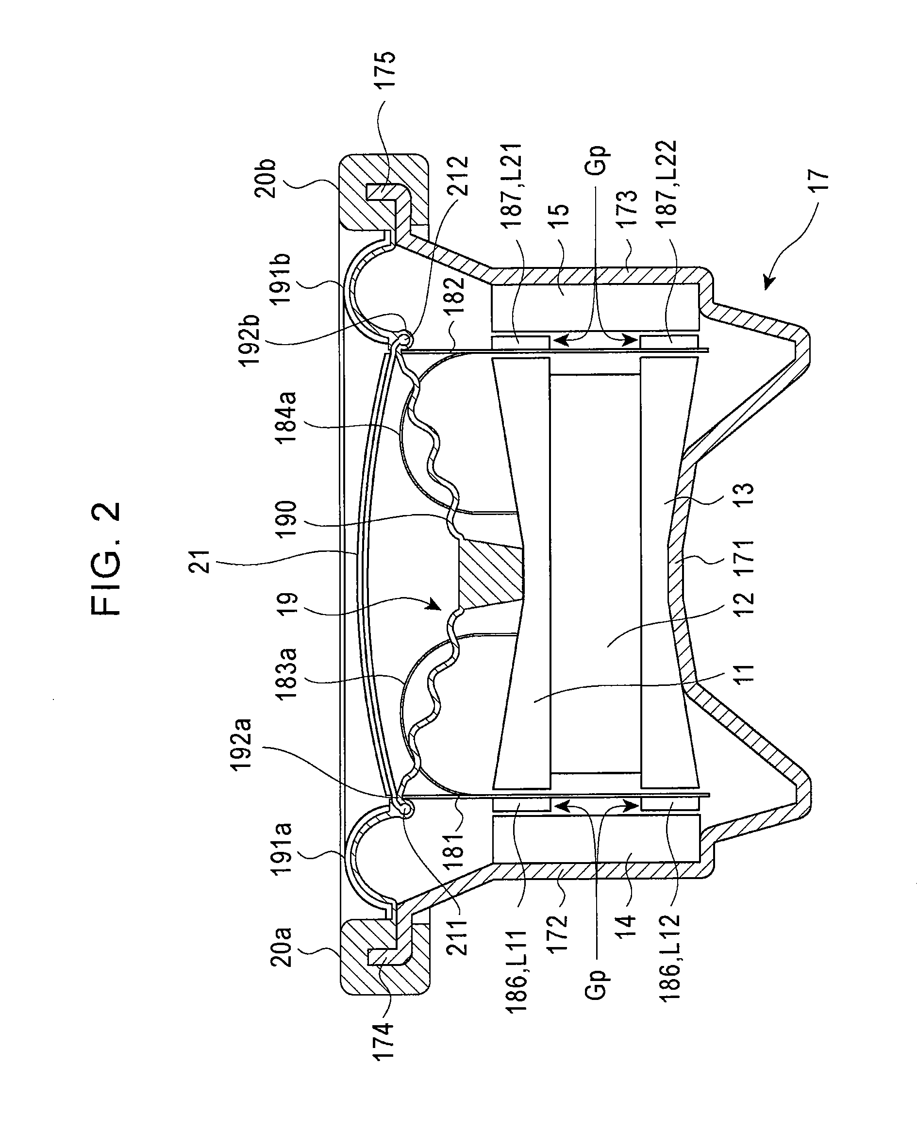
[0094]A speaker device 10 shown in FIG. 1 is an angular shaped speaker device, is configured with the parts shown in FIGS. 3 through 12, and has the cross-sectional configuration as shown in FIG. 2. Specifically, the speaker device 10 is formed by assembling the various parts of a rectangular plate-shaped metallic first inner yoke 11 shown in FIG. 3, a rectangular plate-shaped magnetic plate 12 shown in FIG. 4, a rectangular plate-shaped metallic second inner yoke 13 shown in FIG. 5, a first position-determining member 16a made of a non-magnetic body (for example, a resin) shown in FIG. 6A, a second positioning member 16b made of a non-magnetic body (for example, a resin) shown in FIG. 6B, a first outer yoke 14 and a second outer yoke 15 shown in FIG. 7, a frame member 17 shown in FIG...

second embodiment

[0167]With a speaker device 50 as described above, the magnetic circuit is in a state wherein the positions of the inner yoke 51 and the outer yoke 52 are determined by the first positioning member 53a and the second positioning member 53b so that the magnetic gap Gp is formed, whereby the magnetic plate 12, the inner yoke 51, and the outer yoke 52 have an integrated configuration, and so the magnetic circuit can be assembled in a workable manner by the first positioning member 53a and the second positioning member 53b. Further, other parts, specifically the voice coil unit 56, and the first horizontal edge unit 22a and the second horizontal edge unit 22b are also attached to the first positioning member 53a and the second positioning member 53b, whereby the assembly workability is further improved.

[0168]Also, the positions of the inner yoke 51 and the outer yoke 52 are determined by the first positioning member 53a and the second positioning member 53b, whereby even if the positio...


PUM


Abstract

A speaker device has a magnet, outer yokes, and inner yokes which are assembled so that a magnetic gap is formed between the outer yoke and inner yokes over which a magnetic flux which is generated from the magnet cuts across. A voice coil unit which is linked to a diaphragm is disposed within the magnetic gap, and positioning members determine the positions of the inner yokes and the outer yokes which attach magnetically to the magnet such that a magnetic gap is formed. The speaker device has a magnetic circuit of which the construction facilitates assembly, and recycling of various individual parts is relatively easy.

Description

RELATED APPLICATION[0001]The present application claims priority to Japanese Patent Application Number 2009-277627, filed Dec. 7, 2009, the entirety of which is hereby incorporated by reference.BACKGROUND OF THE INVENTION[0002]1. Field of the Invention[0003]The present invention relates to a speaker device that outputs sound by causing vibration of a diaphragm which is connected to a voice coil by mutual action between a magnetic field generated in a magnetic circuit and an audio signal current that flows through the voice coil.[0004]2. Description of the Related Art[0005]Heretofore, a speaker device having an angular and long, thin configuration has been proposed (see Japanese Unexamined Patent Application Publication No. 2003-32786). This speaker device has a configuration wherein a frame having a rectangular flat-face shape contains a magnetic circuit having a pair of rectangular magnets arrayed so as to sandwich a pole piece on a rectangular-shaped yoke having a horizontally elo...

Claims


Application Information

Patent Timeline
IPC IPC(8): H04R1/00
CPCH04R1/06H04R7/12H04R7/20H04R9/025H04R9/043H04R2400/11H04R2209/041H04R2231/003H04R2307/021H04R2307/027H04R31/006
Inventor TANABE, KEI
Owner ALPINE ELECTRONICS INC
Why Eureka
Try Eureka