Fresh air inlet for an aircraft

a technology for fresh air inlets and aircraft, which is applied in the direction of air intakes of naca type, transportation and packaging, energy-saving board measures, etc., can solve the problems of increasing the complexity of such a fresh air inlet system, the need for protection of fresh air inlets,

Active Publication Date: 2011-06-09
AIRBUS OPERATIONS GMBH
View PDF17 Cites 28 Cited by
  • Summary
  • Abstract
  • Description
  • Claims
  • Application Information

AI Technical Summary

Problems solved by technology

However, the operation of these secondary air inlets requires mechanically actuated flaps or shutters that seal the secondary air inlets during the flight.
In the use of the above-described fresh air inlets, it is furthermore disadvantageous that these fresh air inlets need to be protected from dust and small objects being swirled around during operating phases near the ground, wherein this is usually realized with a deflector shield.
This additional mechanical device increases the complexity of such a fresh air inlet system.

Method used


Image

  • Fresh air inlet for an aircraft
  • Fresh air inlet for an aircraft
  • Fresh air inlet for an aircraft

Examples


Embodiment Construction

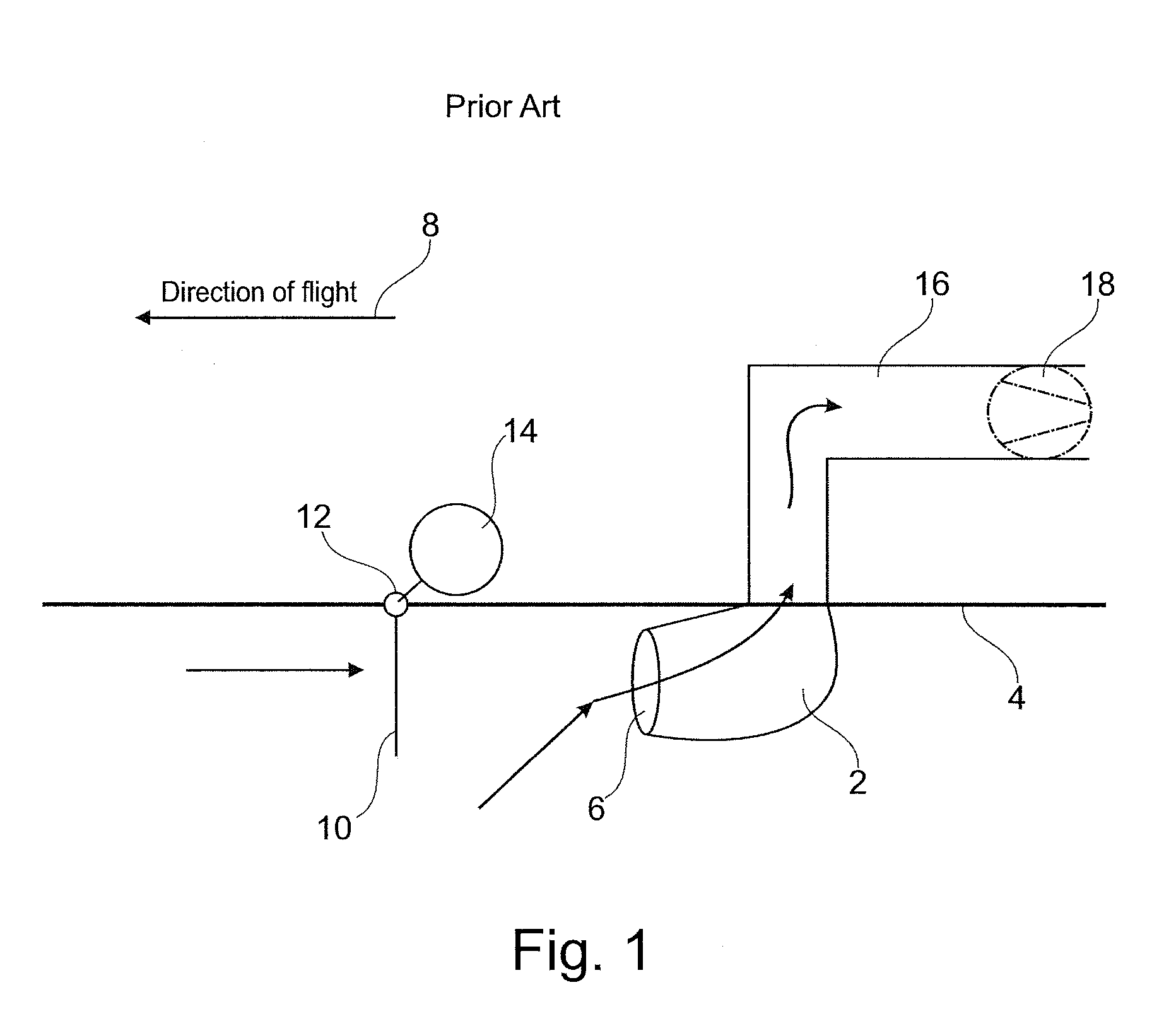
[0038]FIG. 1 shows a fresh air inlet 2 according to the prior art that is located, for example, on the underside of an aircraft fuselage 4. The fresh air inlet 2 features a ram air inlet opening 6 that points in the direction of flight 8. A deflector shield 10 is arranged upstream of the ram air inlet opening 6 and mounted on the aircraft fuselage 4 such that it can be pivoted about a hinge 12. An actuator 14 is connected to the deflector shield 10 in order to realize the pivoting movement thereof. In the illustration shown, the deflector shield 10 is extended and protrudes outward from the surface of the aircraft fuselage 4. Objects that move toward the ram air inlet 2 opposite to the direction of flight 8 are held back by the deflector shield 10. These objects may consist, for example, of foreign matter in the form of the particles, dust or the like. A ram air duct 16 is connected to the fresh air inlet 2 in order to convey ram air introduced into the ram air inlet 2 through the r...


PUM


Abstract

The invention relates to a fresh air inlet for an aircraft that features at least one ram air inlet with at least one ram air inlet opening, at least one secondary air inlet opening that is spaced apart from the ram air inlet and at least one movably mounted flap, wherein the flap can be moved into a first position and into a second position, and wherein the flap essentially covers the secondary air inlet opening in the first position and at least partially opens the secondary air inlet opening and at least in certain areas extends into the air flow directed toward the ram air inlet opening in order to shield the ram air inlet opening from foreign matter in the second position. The air inlet according to the invention makes it possible to reduce the pressure loss of the air inlet on the ground or during flight phases with relatively slow speed due to the enlarged cross-sectional surface. This results in that the actual ram air inlet can be optimized for cruising phases, and that the energy expenditure for any downstream compressors and flow-induced noises can be considerably reduced.

Description

REFERENCE TO RELATED APPLICATIONS[0001]This application claims the benefit of the filing date of U.S. Provisional patent application No. 61 / 130,451, filed May 30, 2008, and of German Patent Application No. 10 2008 026 117.3, filed May 30, 2008 the disclosure of which applications is hereby incorporated herein by reference.FIELD OF THE INVENTION[0002]The invention relates to a fresh air inlet for an aircraft.BACKGROUND OF THE INVENTION[0003]Commercial aircraft require a fresh air supply. This air can be provided by various sources such as an engine compressor, an auxiliary power unit (“APU”) or other sources. It is common practice to supply environmental control systems in larger aircraft with bleed air from aircraft engines. Air-conditioning units of popular aircraft environmental control systems comprise one or more large-volume heat exchangers, through which ram air flows during the flight. The ram air is used for cooling the bleed air. The ram air is usually supplied through ram ...

Claims


Application Information

Patent Timeline
Patent Type & Authority Applications(United States)
IPC IPC(8): B64D13/00
CPCB64C7/00B64D13/00B64D2033/022B64D33/02Y02T50/44Y02T50/56B64D2241/00Y02T50/40Y02T50/50
Inventor EICHHOLZ, JOHANNESBEIER, JENSSOLNTSEV, ALEXANDERSCHMIDT, RUEDIGER
Owner AIRBUS OPERATIONS GMBH
Why Eureka
Try Eureka