Periprosthetic bone plates
- Summary
- Abstract
- Description
- Claims
- Application Information
AI Technical Summary
Benefits of technology
Problems solved by technology
Method used
Image
Examples
Embodiment Construction
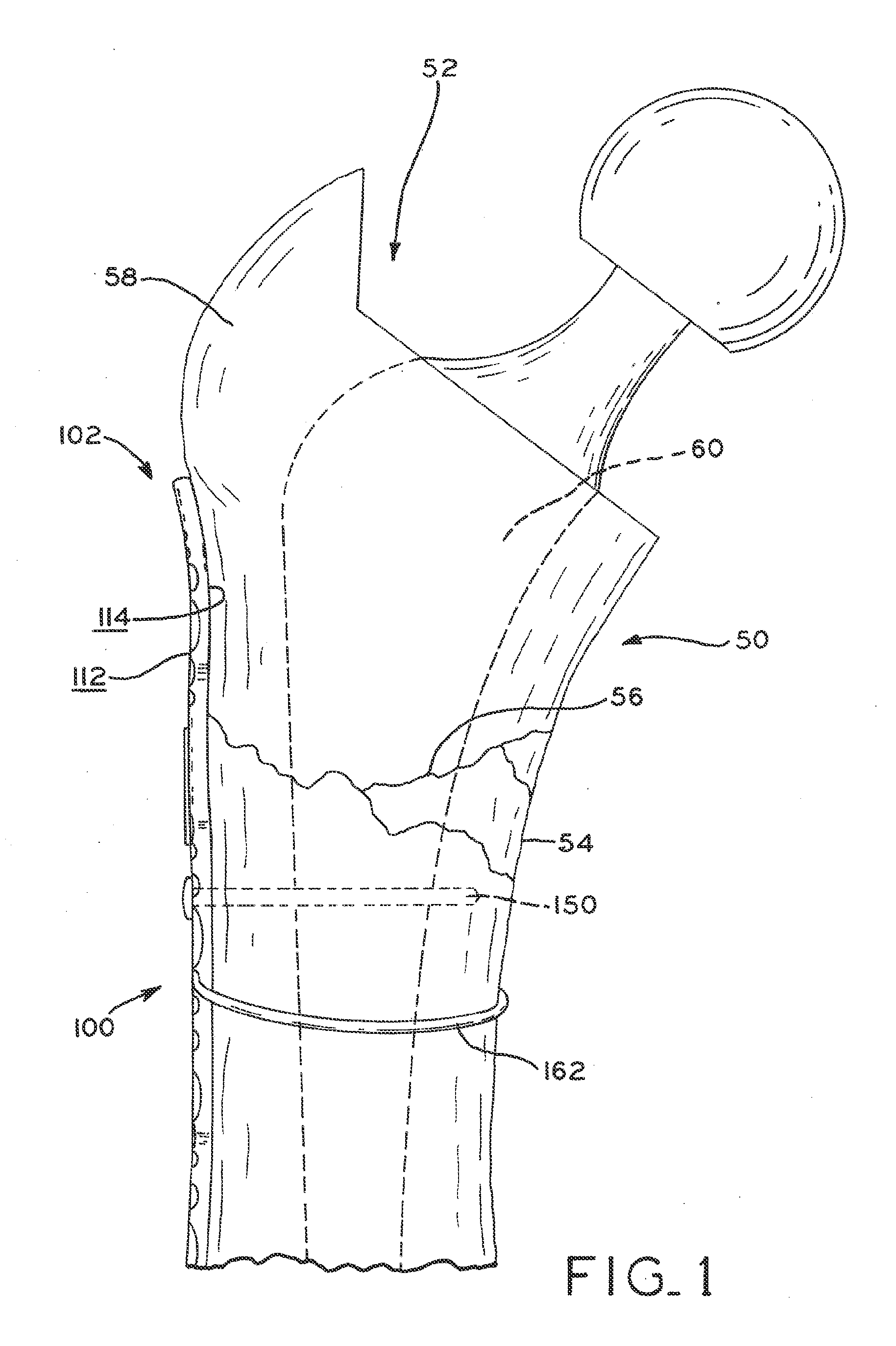
[0032]FIG. 1 depicts a patient's proximal femur 50 having proximal end 52, a distal end (not shown), and shaft 54 extending therebetween. Shaft 54 of femur 50 includes fracture 56. In the illustrated embodiment, a prosthetic component, specifically femoral stem 60 of a hip replacement system, is implanted into the patient's proximal femur 50. As shown in FIG. 1, fracture 56 in femur 50 is located adjacent to femoral stem 60.
[0033]As shown in FIG. 1, bone plate 100 is secured onto shaft 54 of femur 50 to extend across fracture 56. Although bone plate 100 is described and depicted herein as being secured onto a patient's femur 50, bone plate 100 may be sized for securement onto a patient's tibia, fibula, humerus, radius, ulna, or another long bone.
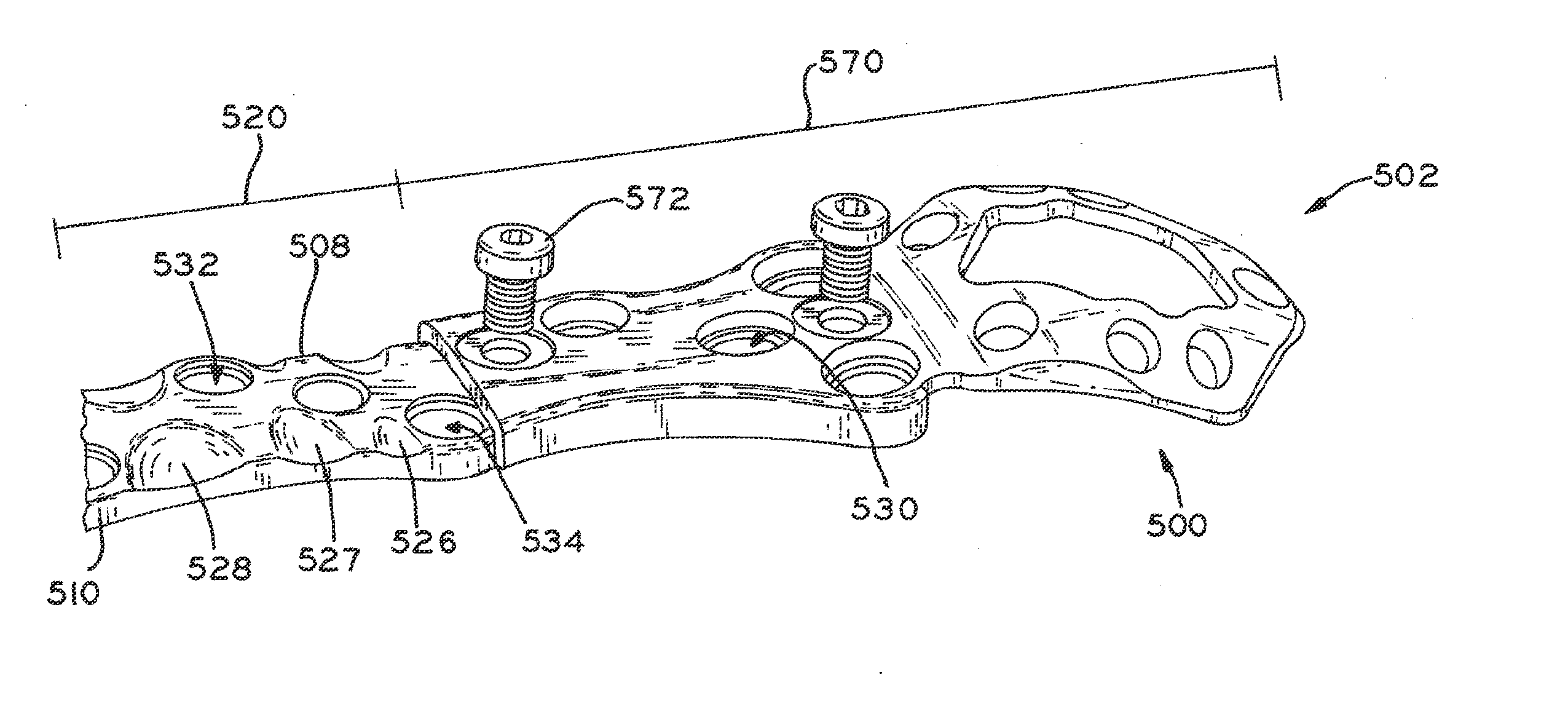
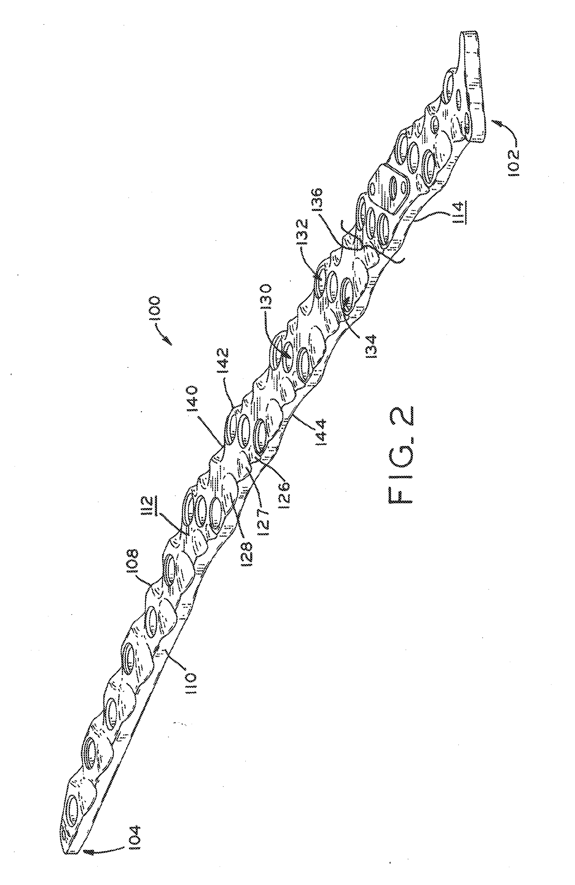
[0034]Referring to FIGS. 2-4, bone plate 100 of the present invention is provided for use on proximal end 52 of femur 50. Bone plate 100 is configured for use on a patient's left leg, although a mirror image plate may be provided for use on ...
PUM
 Abstract
Description
Claims
Application Information
 - R&D
- Intellectual Property
- Life Sciences
- Materials
- Tech Scout
- Unparalleled Data Quality
- Higher Quality Content
- 60% Fewer Hallucinations
Browse by: Latest US Patents, China's latest patents, Technical Efficacy Thesaurus, Application Domain, Technology Topic, Popular Technical Reports.
© 2025 PatSnap. All rights reserved.Legal|Privacy policy|Modern Slavery Act Transparency Statement|Sitemap|About US| Contact US: help@patsnap.com


