
Design Optimization System

a design optimization and system technology, applied in multi-objective optimization, instruments, cad techniques, etc., can solve the problems of merely addressing all variables in a single analysis, requiring either reanalysis or accepted inefficiencies, and a large number of steps and processes for the design of complex products

Active Publication Date: 2011-06-09
NITED STATES STEEL CORP +1
View PDF16 Cites 77 Cited by
  • Summary
  • Abstract
  • Description
  • Claims
  • Application Information

AI Technical Summary

Benefits of technology

The present invention provides a method for designing complex products by automatically generating a base design analysis model and performing topology optimization to identify critical structure areas and load paths. A multi-disciplinary 3G optimization is then performed to optimize shape, thickness, and material for a plurality of loading conditions. The optimized structure is then modified to comply with manufacture requirements. The technical effect of this invention is to provide a more efficient and effective method for designing complex products.

Problems solved by technology

The design of complex products commonly requires a large number of steps and processes.
Changes from the designers, changes from manufacturing feasibility, changes from engineering requirements all impact each other and commonly require either reanalysis or accepted inefficiencies.
In complex structures such as vehicle design, merely addressing all variables in a single analysis would be virtually untenable with modern processing limitations.

Method used


Image

  • Design Optimization System
  • Design Optimization System
  • Design Optimization System

Examples


Embodiment Construction

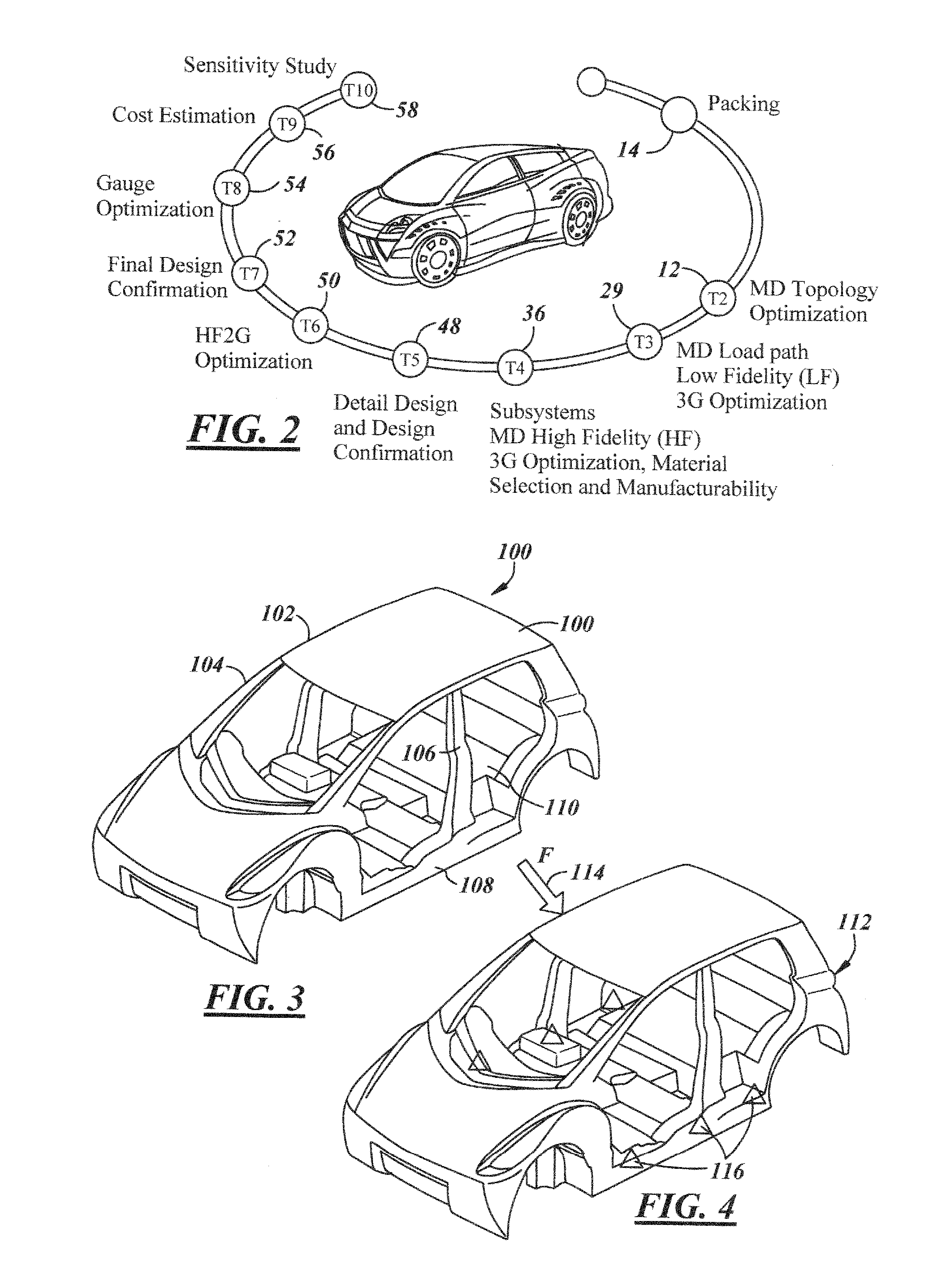
Referring now to the attached Figures which are various details and descriptions of the present invention. The present invention is directed to a system and method for accelerated concept to product design process. The present invention was developed and intended for the development of automotive designs that are approached and designed from a holistic design optimization process. Although the description and attachments are directed towards the development of automotive body structures, one skilled in the art would be able to apply the methodology to a wide variety of products in light of the present disclosure.

The present invention contemplates the methodology to be capable of being integrated into a single piece of software. In addition, the present invention contemplates a plurality of interactive software programs or modules. Finally, the methodology of the design process alone can be implemented without regard to the software base.

The present invention synchronizes computer ai...


PUM


Abstract

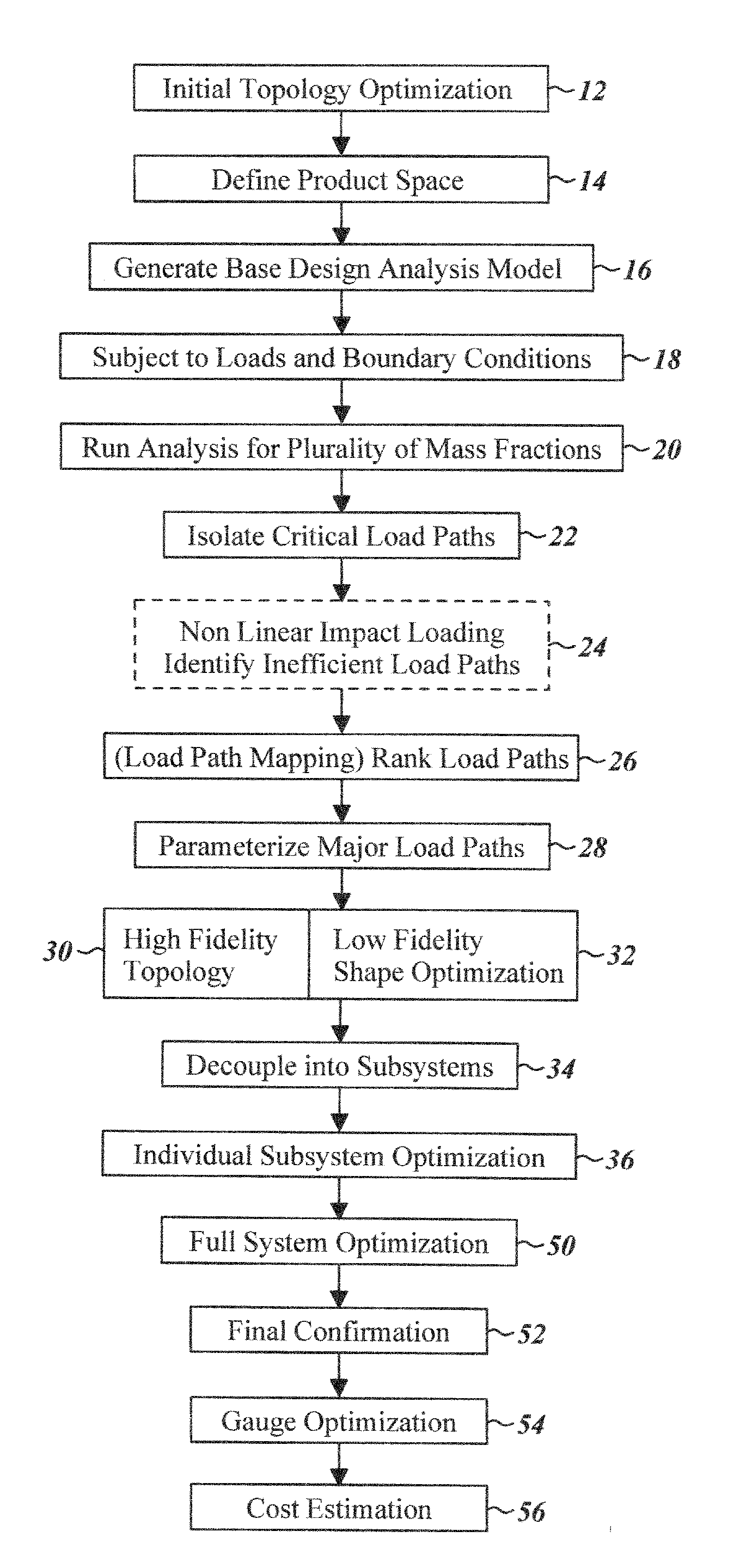
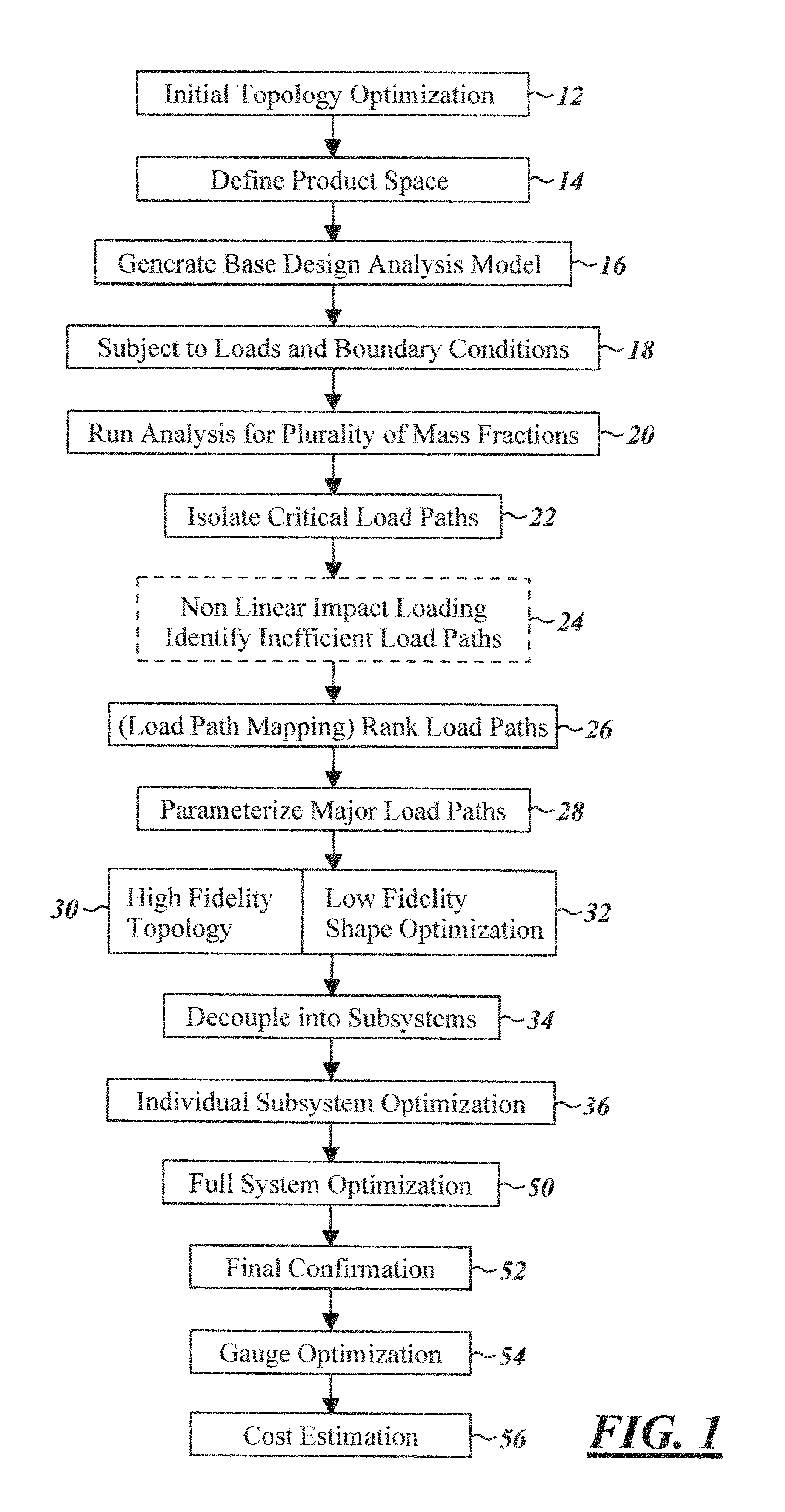
In accordance with the objects of the present invention, a method of complex product design is provided. The method defines a product design space a base design analysis model is then automatically generated within the product design space. A topology optimization of the base design analysis model is performed including solving the topology optimization for multiple mass fractions to identify critical structure areas. The results of the topology optimizations are utilized to identify a plurality of load paths. An optimization of said plurality of load paths is performed to find the optimized load paths. Critical structure areas along the plurality of optimized load paths are then parameterized. An optimization is performed utilizing a multi-disciplinary optimization to optimize geometry, material and thickness along the optimized load paths. A manufacturing analysis of the shape optimized structure is performed and the shape optimized structure is modified to comply with manufacture requirements. An optimization is then performed using multi-disciplinary optimization comprising a gauge and grade optimization.

Description

TECHNICAL FIELDThe present invention relates generally to a method and system for generating optimized designs and more particular to a method and system for integrating multi-disciplinary optimization into concept design.BACKGROUND OF THE INVENTIONThe design of complex products commonly requires a large number of steps and processes. Commonly product design begins with artistic concept rendering; moves into CAD drawings; is analyzed for structural integrity using computer aided engineering; is analyzed for manufacturing feasibility; is reanalyzed for structural integrity; is re-evaluated for design change acceptability. Each step is approached independently often by a different group of specialists. Changes from the designers, changes from manufacturing feasibility, changes from engineering requirements all impact each other and commonly require either reanalysis or accepted inefficiencies.This is exceedingly prevalent in the design of complex structures such as automobiles. Automo...

Claims


Application Information

Patent Timeline
Patent Type & Authority Applications(United States)
IPC IPC(8): G06F17/50G06F19/00
CPCG06F17/5009G06F2217/08G06F17/5095G06F30/15G06F30/20G06F2111/06
Inventor FARAHANI, AKBAR
Owner NITED STATES STEEL CORP
Learn More