Method and kit for dental implant drilling guides

a technology for dental implants and drilling guides, applied in the field of dental implants and methods and kits, can solve the problems of complex and risky implant installation, difficult work of lower jaw bones, and difficulty in accidental drilling into sinus regions, and achieve the effect of quick production

Inactive Publication Date: 2012-10-04
KATZ HOWARD IAN
View PDF11 Cites 10 Cited by
  • Summary
  • Abstract
  • Description
  • Claims
  • Application Information

AI Technical Summary

Benefits of technology

[0014]The present invention is based, in part, on the insight that the patient's natural tooth socket, and in particular the hole in the bone (root socket, extraction socket) left over when the patient's natural tooth root has been extracted, either itself a good location to subsequently locate an implant screw (at least once this natural root socket has filled in with new bone) or is at least an excellent reference point by which to locate the subsequent implant screw. This is because natural tooth root, originally avoided any critical structures such as nerves, and was usually well positioned with respect to the other surrounding bone. To the extent that the natural tooth root location is less than optimal, often an excellent implant screw location can be found by a simple angle or distance offset from the original natural tooth socket.
[0025]When the practitioner then desires to drill the dental implant socket, the guide, often in conjunction with the X-ray post depth information, can be used to direct drilling along the same route as the old tooth root, thus avoiding critical structures.

Problems solved by technology

However if, as is often the case, an inadequate amount of natural bone remains in the tooth socket after extraction of the natural root, the empty tooth socket may have to be first filled with artificial bone material.
In practice, installing implants is both complex and risky because there is little tolerance for error in the drilling step.
For example the bones of the upper jaw border on the delicate open sinus structures, and accidentally drilling into the sinus region is of course very bad.
The bones of the lower jaw are also tricky to work with.
In addition to the risk of the drill bit accidently extending outside the lower jaw bone, there are also various lower jaw structures, such nerve canals, blood vessels, and the like, where accidental drilling can cause substantial permanent damage to the patient.
As a result, general dentists who may be otherwise comfortable with other parts of the implant process, such as tooth extraction, filling up tooth sockets with artificial bone, and installing artificial crowns into previously installed implant roots, are often reluctant to do implant drilling.
Unfortunately, the general dentist is in a difficult conflict of interest situation here.
This is because as a result of the implant referral, the general dentist will lose out on the subsequent implant revenue from that patient.
Thus at present, implants, although they may give superior results, tend to be a bit underused.
Such computerized tomography devices and 3D fabrication methods are very expensive, and as a result, implant guides alone can often cost around $1000 or more.
As another alternative, the dentist, oral surgeon, or peridontist can attempt to drill guided only by professional judgment and standard dental X-rays, and assume the risk of problems and complications that may result.
Unfortunately Tang fails to suggest how such a template may be oriented properly with respect to critical structures in the patient's jaw.
As a result, there is a strong disconnect between the process of tooth extraction and the beginning of the implant process.
This disconnect adds a substantial amount of expense to the dental implant process, and often results in patients being encouraged to adopt less optimal solutions, such as dental bridges.

Method used


Image

  • Method and kit for dental implant drilling guides
  • Method and kit for dental implant drilling guides
  • Method and kit for dental implant drilling guides

Examples


Embodiment Construction

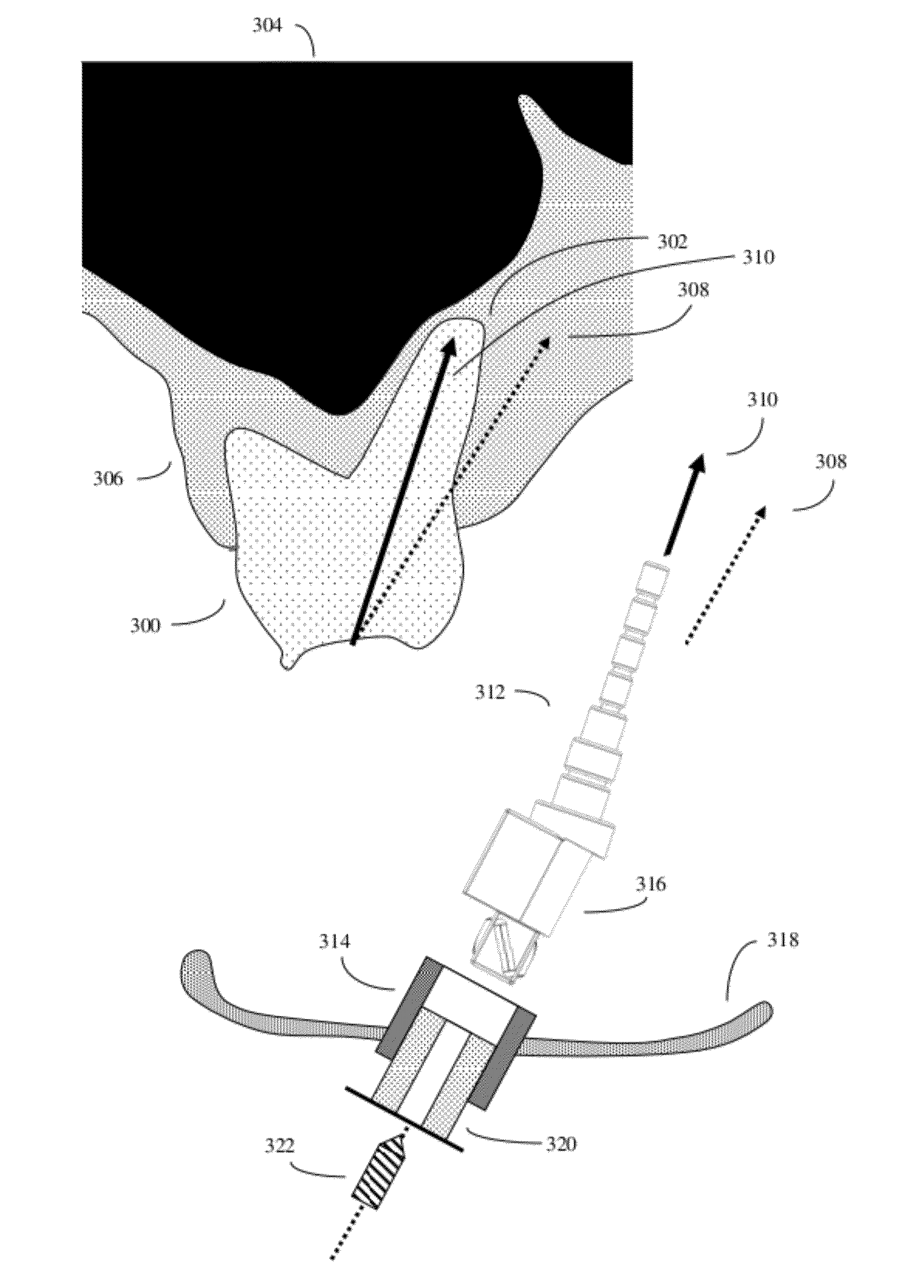
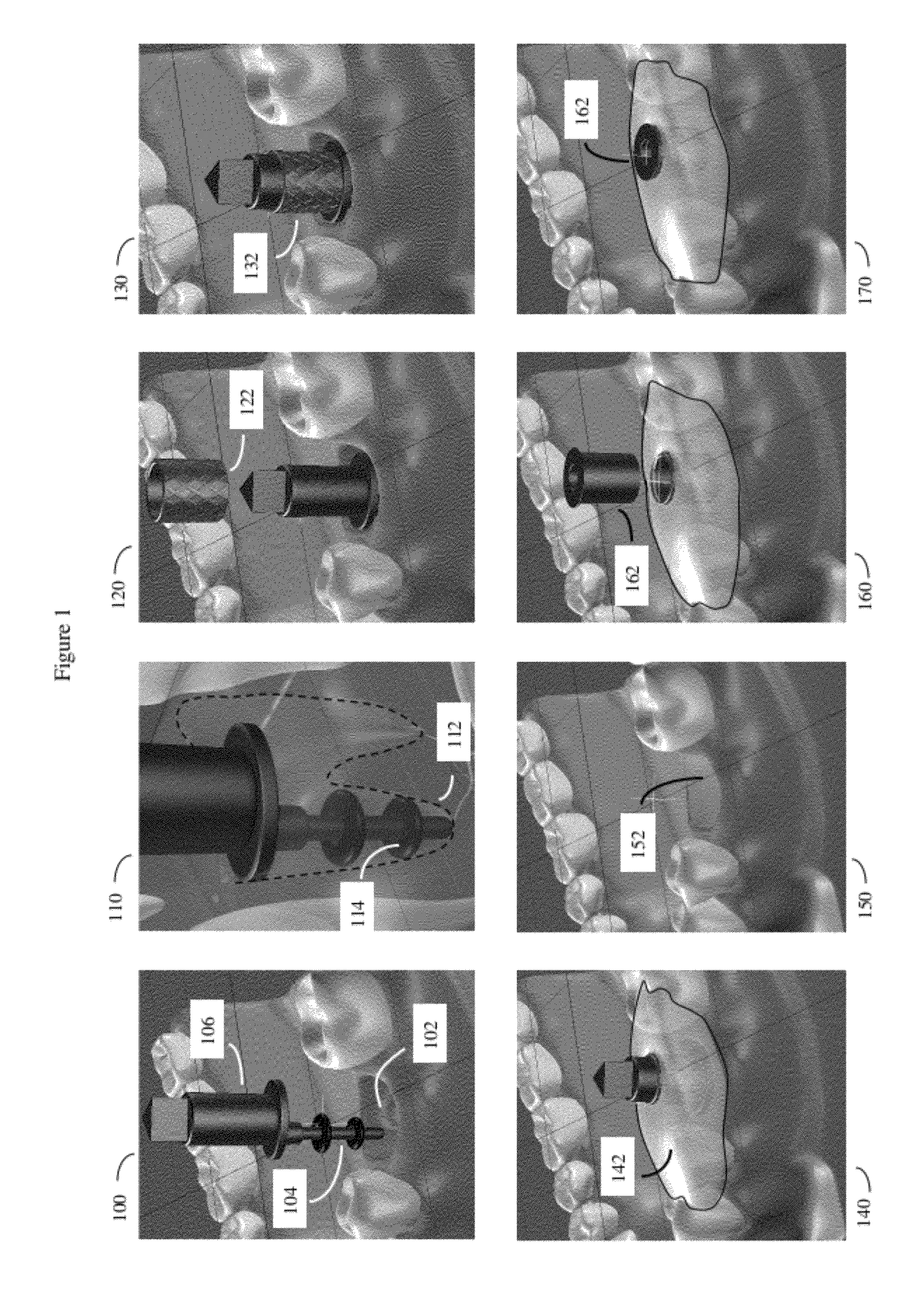
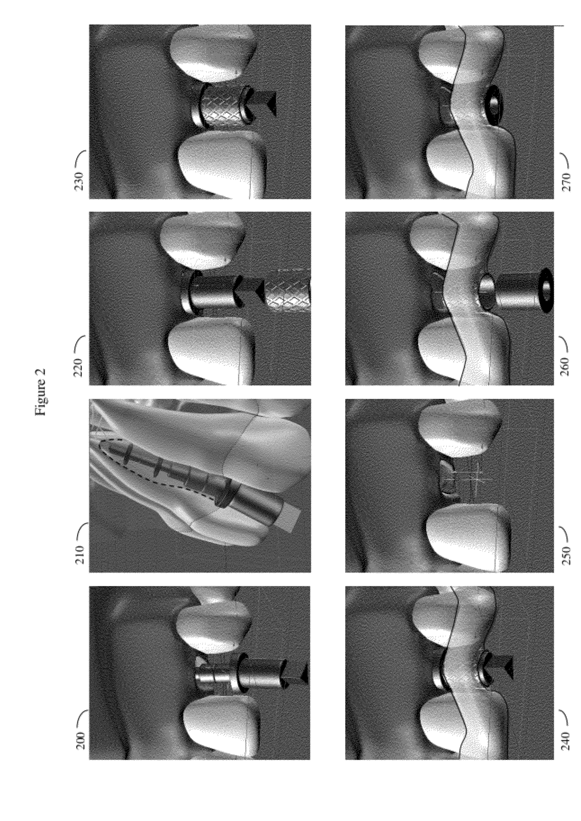
[0037]In one embodiment, the invention may be a method of aligning a dental implant based upon the position and depth of the natural tooth socket at the time of tooth extraction. The invention may also be a kit of components to accomplish this method. The method will generally comprise or at least start by extracting a tooth from the jaw of a human patient. This patient will generally have a fair number of other teeth, usually including other teeth reasonably adjacent to the empty tooth socket left in the patient's jaw, after the tooth has been extracted.

[0038]After this extraction, there will typically remain an extraction socket in the patient's jaw bone, and this extraction socket will in turn typically contain at least one tooth root socket in the jaw bone corresponding to the position of at least one root of the extracted tooth.

[0039]According to the method, while the extraction socket remains open and unhealed, a post device is placed into this at least one tooth root socket. ...


PUM


Abstract

Method and kit for producing implant drilling guides positioned at the proper orientation to avoid inadvertent damage to critical regions of the patient's jaw when drilling to place dental implant screws. The method works by placing a small post device with x-ray visible depth markers in the root socket of the patient's tooth immediately after tooth extraction. The post device may additionally be configured to guide the drill at a position and angle that is different from that of the original tooth socket. This post device is used to construct a removable guide that anchors to the patient's adjacent teeth, and preserves the location and orientation of the extracted tooth root. Once the root socket is filled in with new bone, the guide, in conjunction with the X-ray post depth information, can be used to direct drilling along the same route as the old tooth root, thus avoiding critical structures.

Description

CROSS REFERENCE TO RELATED APPLICATIONS[0001]This application is a continuation in part of patent application Ser. No. 13 / 183,386, METHOD AND KIT FOR PRODUCING DENTAL IMPLANT DRILLING GUIDES “, filed Jul. 14, 2011, inventor Howard Ian Katz; both Ser. No. 13 / 183,386 and this application claim the priority benefit of provisional patent application 61 / 468,259, “Device that records the exact spatial position, location in the jawbone, root socket depth and orientation of a recently extracted tooth that may be used to locate an ideal site to replace a tooth. It measures the location and dimensions of a tooth socket seconds after a tooth has been extracted before the socket has began to heal”, inventor Howard Ian Katz, filed Mar. 28, 2011; both Ser. No. 13 / 183,386 and this application also claim the priority benefit of provisional patent application 61 / 507,945, “METHOD AND KIT FOR PRODUCING DENTAL IMPLANT DRILLING GUIDES”, inventor Howard Ian Katz, filed Jul. 14, 2011.BACKGROUND OF THE INV...

Claims


Application Information

Patent Timeline
Patent Type & Authority Applications(United States)
IPC IPC(8): A61C8/00A61C1/08
CPCA61C1/084A61C8/0089A61C8/0001
Inventor KATZ, HOWARD IAN
Owner KATZ HOWARD IAN
Why Eureka
Try Eureka