Method for Continuously and Adaptively Generating a Speed Setpoint for an Aircraft to Observe an RTA

a technology of setpoints and aircraft, applied in the direction of process and machine control, instruments, navigation instruments, etc., can solve the problems of difficult convergence of index calculation and difficulty in sufficiently responsive compensation for any drift, and achieve the effect of sufficient margins

Active Publication Date: 2011-06-09
THALES SA
View PDF17 Cites 18 Cited by
  • Summary
  • Abstract
  • Description
  • Claims
  • Application Information

AI Technical Summary

Benefits of technology

[0013]Another advantage of the invention is that it allows for the application of various strategies for generating the speed setpoint, to ensure sufficient margins for satisfying the time constraint, in particular in the case of unstable or imprecise wind, and optimize the speed profile according to the different flight phases and / or according to the distance relative to the point at which the RTA constraint is applied.
[0017]application at any point of curvilinear abscissa X of the flight plan of a speed setpoint VΩ(X) of the aircraft determined on the basis of the speed profiles Vmin(X) and Vmax(X) weighted by proportionality ratios between T(X), TVmin(X) and TVmax(X);
[0018]In one embodiment of the invention, the method for generating a flight speed profile of an aircraft can be characterized in that, for the current position of the aircraft along the flight plan, an additional optimum speed reference speed profile Vopt(X) is determined according to at least one defined flight criterion, the speed profile of the aircraft being constrained to tend towards the optimum speed profile Vopt(X) by the addition to the RTA of a tolerance ΔT the sign of which is opposite to the sign of the difference between the time of passage of the aircraft at the current position and the corresponding time of passage TVopt(X), until the absolute value of the difference between T(X) and TVopt(X) is less than a maximum time difference δt, the RTA then being restored to its initial value.
[0019]In one embodiment of the invention, said at least one defined flight criterion can comprise a cost index.
[0020]In one embodiment of the invention, said at least one defined flight criterion can comprise a performance index.
[0021]In one embodiment of the invention, the method for generating a flight speed profile of an aircraft can be characterized in that the speed setpoint VΩ(X) is determined by the relation:

Problems solved by technology

Such a method has a certain number of drawbacks:determining the speed profile with which to observe the RTA requires a number of iterations that may be high, the number of iterations being relatively unpredictable and variable from one calculation to another;in some cases, the convergence of the calculation of the index is difficult, because of complex behaviours of the function linking the performance index to the time of passage at the point at which the RTA is applied;if there is a drift during a flight relative to the calculated profile, for example because of wind gusts or even unexpected aircraft performance levels, it is necessary for the calculation of the speed profile to be repeated in full.
It is also necessary to ensure a relatively short periodicity in the performance of the calculation, in order to keep to precise predictions;on approaching the point at which the RTA is applied, it becomes difficult to compensate sufficiently responsively for any drifts.

Method used


Image

  • Method for Continuously and Adaptively Generating a Speed Setpoint for an Aircraft to Observe an RTA
  • Method for Continuously and Adaptively Generating a Speed Setpoint for an Aircraft to Observe an RTA
  • Method for Continuously and Adaptively Generating a Speed Setpoint for an Aircraft to Observe an RTA

Examples


Embodiment Construction

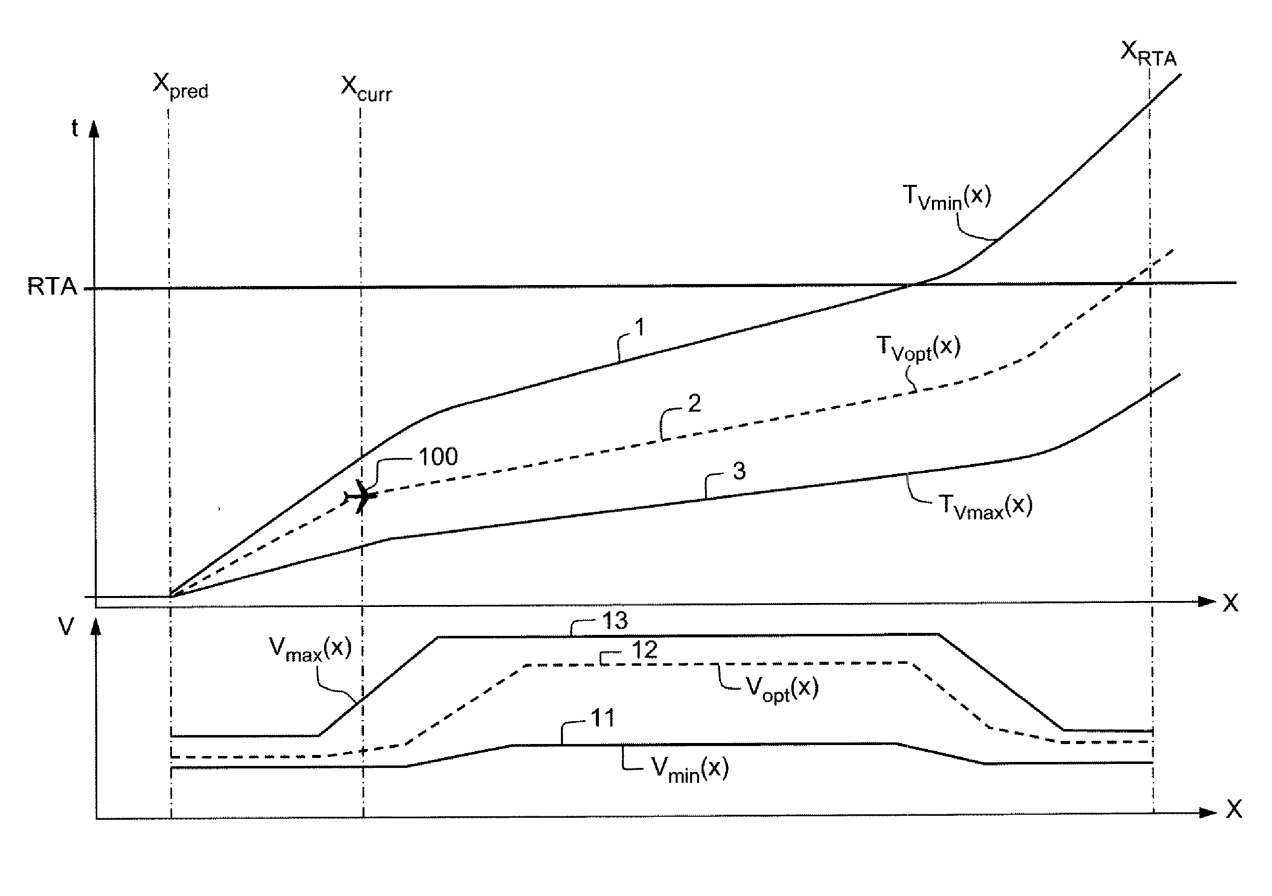
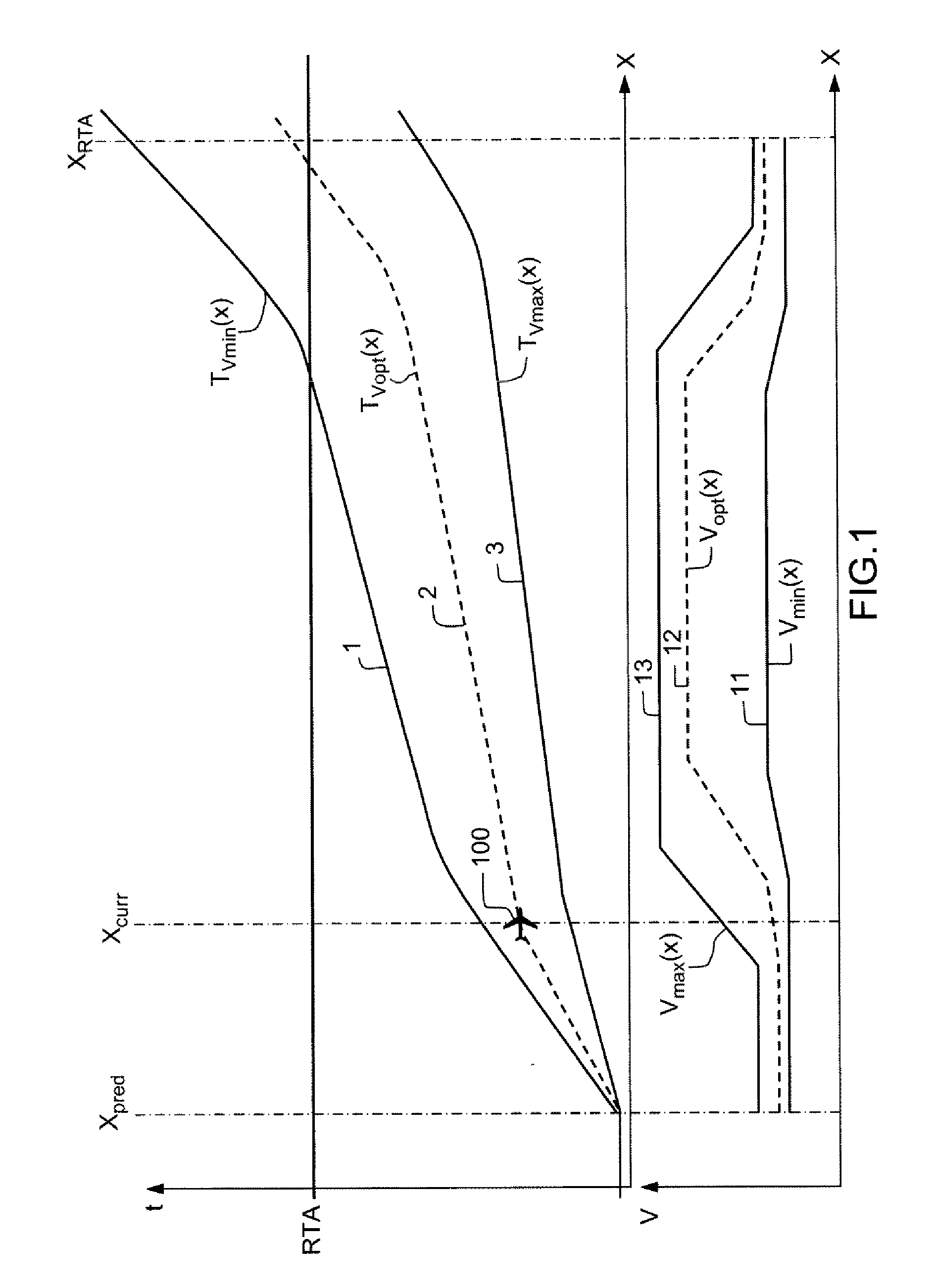
[0038]FIG. 1 shows examples of curves representing the times of passage of an aircraft at curvilinear abscissae along its flight plan, for flights following different speed profiles.

[0039]Hereinafter, the letter X designates the curvilinear abscissa of an aircraft 100, along a flight plan, that is to say, a distance between a point of the flight plan and a reference point of the flight plan. A prediction of the time of passage T(X) of the aircraft 100 at the curvilinear abscissa X is made at an abscissa point Xpred.

[0040]A first curve 1 represents the times of passage ETA_Vmin(X) of the aircraft 100 according to the curvilinear abscissa X, assuming that the latter is moving according to a minimum speed profile Vmin(X) corresponding to the lower limit of the flight envelope along the profile, possibly augmented by an operational margin in order, for example, to limit acceleration inertia at low speeds or even the temporary risks of excessively low speed generated, for example, by win...


PUM


Abstract

Method for generating a flight speed profile of an aircraft (100) according to an RTA constraint, characterized in that it permanently calculates, at any point of the flight plan, a speed setpoint VΩ(X) of the aircraft determined on the basis of reference speed profiles, comprising at least a minimum speed profile Vmin(X), and a maximum speed profile Vmax(X). The method can also take into account an optimum speed profile Vopt(X) determined, for example, on the basis of a cost or performance index.

Description

CROSS-REFERENCE TO RELATED APPLICATIONS[0001]This application claims priority to foreign France patent application No. 0902613, filed on May 29, 2009, the disclosure of which is hereby incorporated by reference in its entirety.FIELD OF THE INVENTION[0002]The present invention relates to a method for continuously and adaptively generating a speed setpoint for an aircraft to observe an RTA. It applies notably to the field of avionics, and more particularly to a flight management device of an aircraft, designated hereinafter by the acronym FMS, standing for Flight Management System.BACKGROUND OF THE INVENTION[0003]In the general context of air traffic, it is a fact that the traffic density is increasing year-on-year. At the same time, it is necessary for the environmental impact of the air traffic to be reduced. Finally, it is necessary for the accident rate to be kept at the current level, or even reduced. Respecting these principles and requirements notably requires the air traffic c...

Claims


Application Information

Patent Timeline
Patent Type & Authority Applications(United States)
IPC IPC(8): G06F7/00G05D1/00
CPCG05D1/101G08G5/0052G08G5/0026
Inventor DACRE-WRIGHT, BENO TDEKER, GUYBLANCHON, XAVIER
Owner THALES SA
Why Eureka
Try Eureka