Exhaust heat recovery for engine heating and exhaust cooling

a technology of exhaust heat recovery and engine heating, applied in the field of heat exchange, can solve the problems of viscous energy loss, higher emissions, energy loss, etc., and achieve the effects of reducing energy loss, reducing heat loss in the combustion chamber, and reducing engine pumping loss

Active Publication Date: 2011-06-16
FORD GLOBAL TECH LLC
View PDF10 Cites 39 Cited by
  • Summary
  • Abstract
  • Description
  • Claims
  • Application Information

AI Technical Summary

Benefits of technology

[0003]Some methods for expediting engine heating include exhaust heat recovery. In some examples, exhaust heat is transferred to engine coolant, for example, via a heat exchanger. Such a method, however, may be only marginally effective in quickly heating the combustion chamber and / or reducing fluid viscosity.
[0005]By heating intake air with exhaust heat and then transferring some of the heat to a powertrain fluid such as engine oil, the fluid may be heated thereby reducing energy losses due to the viscosity of the fluid in addition to reducing combustion chamber heat loss. Further, the heated intake air may be cooled via the heat exchange with the powertrain fluid, yet still be warmer than ambient air such that engine pumping losses may also be reduced, but not so hot that combustion stability is reduced or knock instigated. Further, during warmed-up or boosted operating conditions, for example, heated intake air may cause knock under some conditions; however, during a cold start with the engine warming up, the possibility of the heated intake air causing knock is decreased. As such, a synergistic operation may be achieved.
[0006]Another advantage of the disclosed approach is the warming of the engine coolant with air that has picked up heat from the exhaust can increase the heat available for cabin warming. Further, engines often have oil coolers to mitigate peak oil temperatures for engine used at extreme conditions. Thus, the disclosed approach uses the air-to-oil (e.g., gas-to-liquid) heat exchange to achieve oil cooling by reversing the airflow direction via the increased boost, which occurs precisely at times when engine oil cooling needs arise.

Problems solved by technology

During this time, emissions may be higher and there may be energy losses such as viscous energy losses due to a relatively cool temperature of fluids (e.g., engine oil, transmission fluid, etc.) circulating through the powertrain.
Such a method, however, may be only marginally effective in quickly heating the combustion chamber and / or reducing fluid viscosity.
Further, during warmed-up or boosted operating conditions, for example, heated intake air may cause knock under some conditions; however, during a cold start with the engine warming up, the possibility of the heated intake air causing knock is decreased.

Method used


Image

  • Exhaust heat recovery for engine heating and exhaust cooling
  • Exhaust heat recovery for engine heating and exhaust cooling
  • Exhaust heat recovery for engine heating and exhaust cooling

Examples


Embodiment Construction

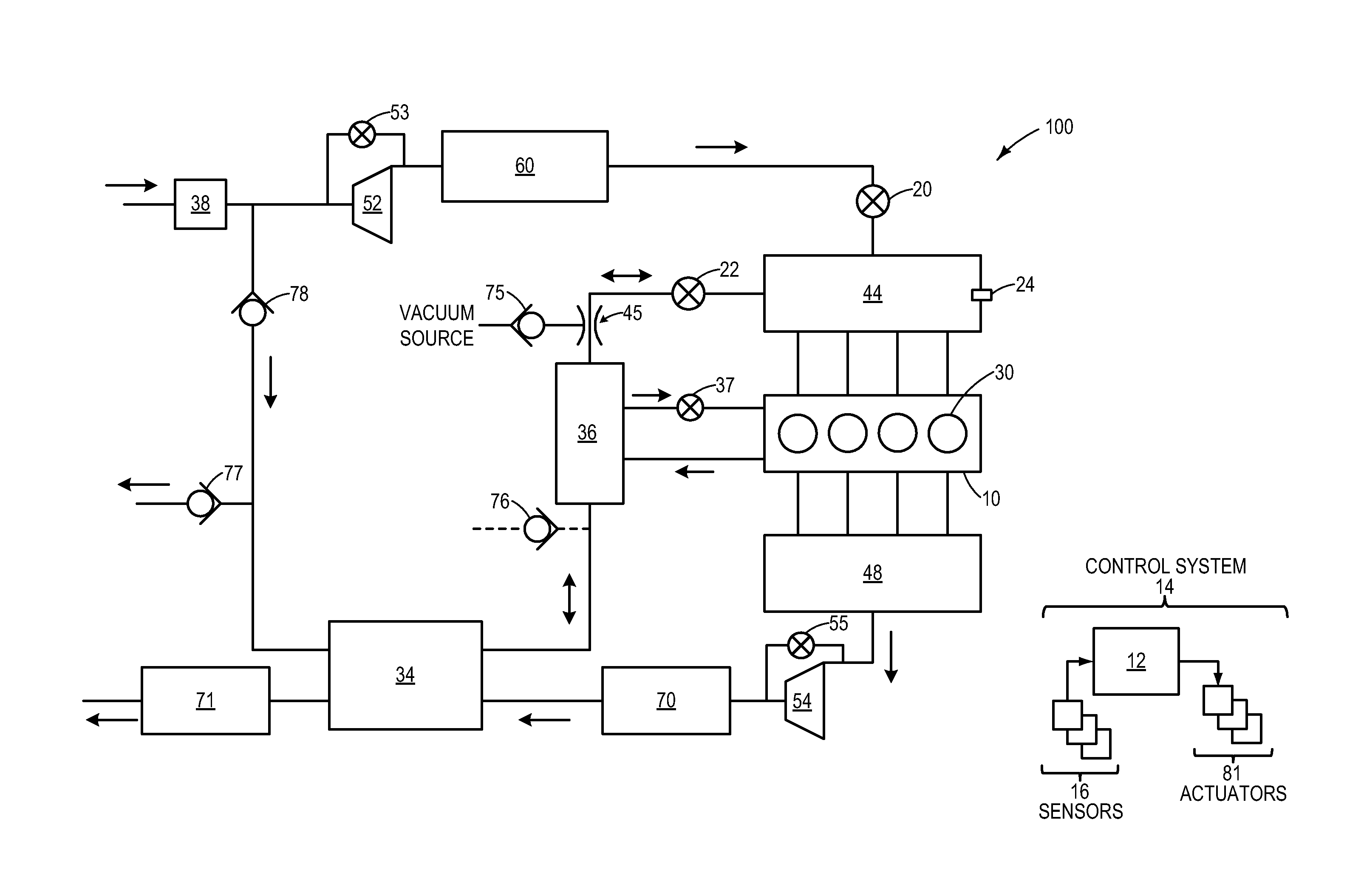
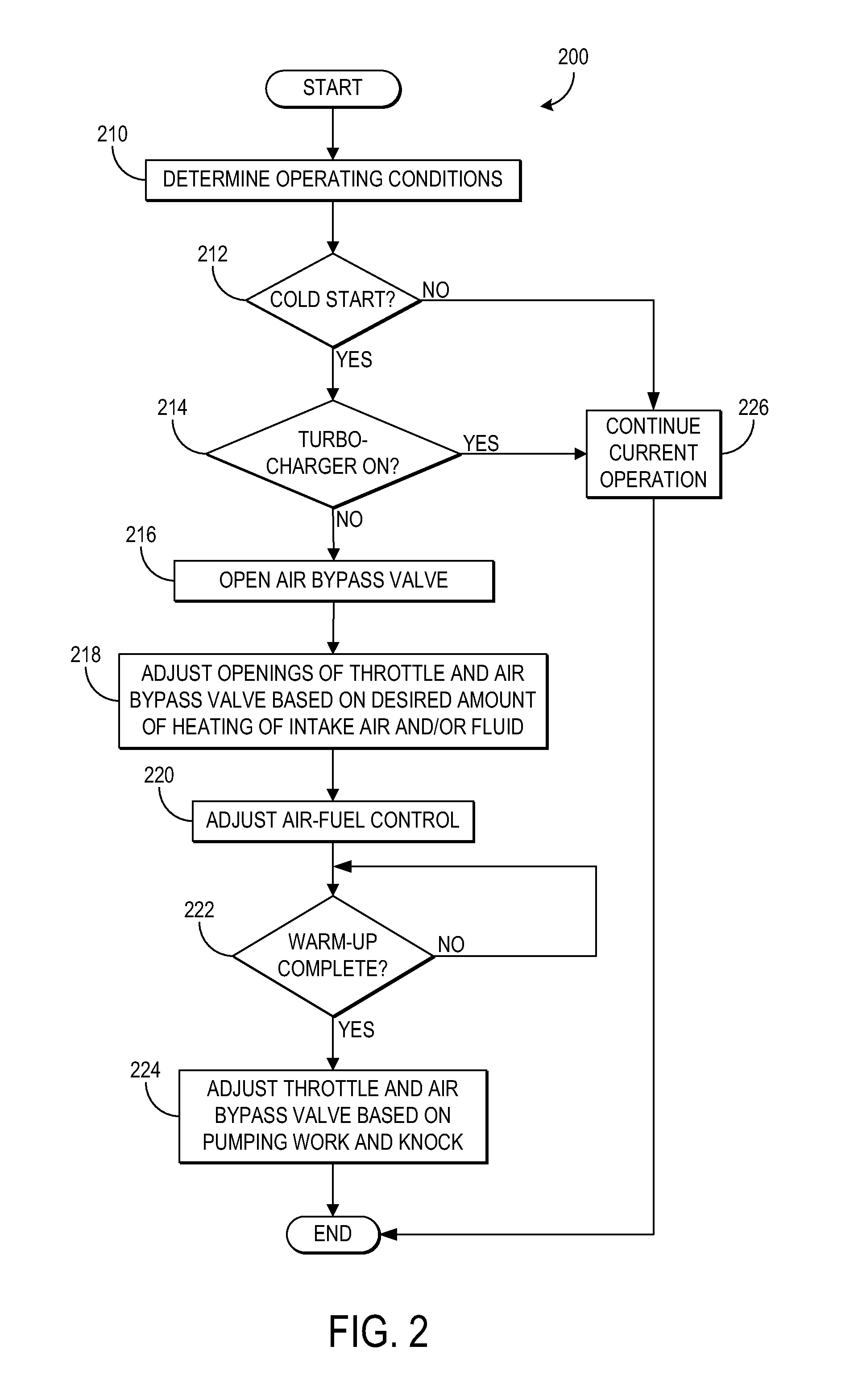
[0011]The following description relates to systems and methods for heating an engine in a vehicle during a cold start. In one example, intake air flowing in a first direction may be heated through a heat exchange with exhaust gas via a gas-to-gas heat exchanger. The heated intake air may subsequently undergo a second heat exchange with a powertrain fluid (e.g., engine oil, transmission fluid, etc.) via a gas-to-liquid heat exchanger such that the powertrain fluid is heated. As such, viscous energy losses due to relatively cold fluid may be reduced, and combustion chamber heat loss and pumping losses are also reduced due to the heated intake air. Furthermore, in another example, when pumping loss reduction and powertrain fluid heating are not desired, but exhaust cooling is desired, intake air may flow through the heat exchangers in a second direction such that the exhaust is cooled for exhaust catalyst cooling, for example.

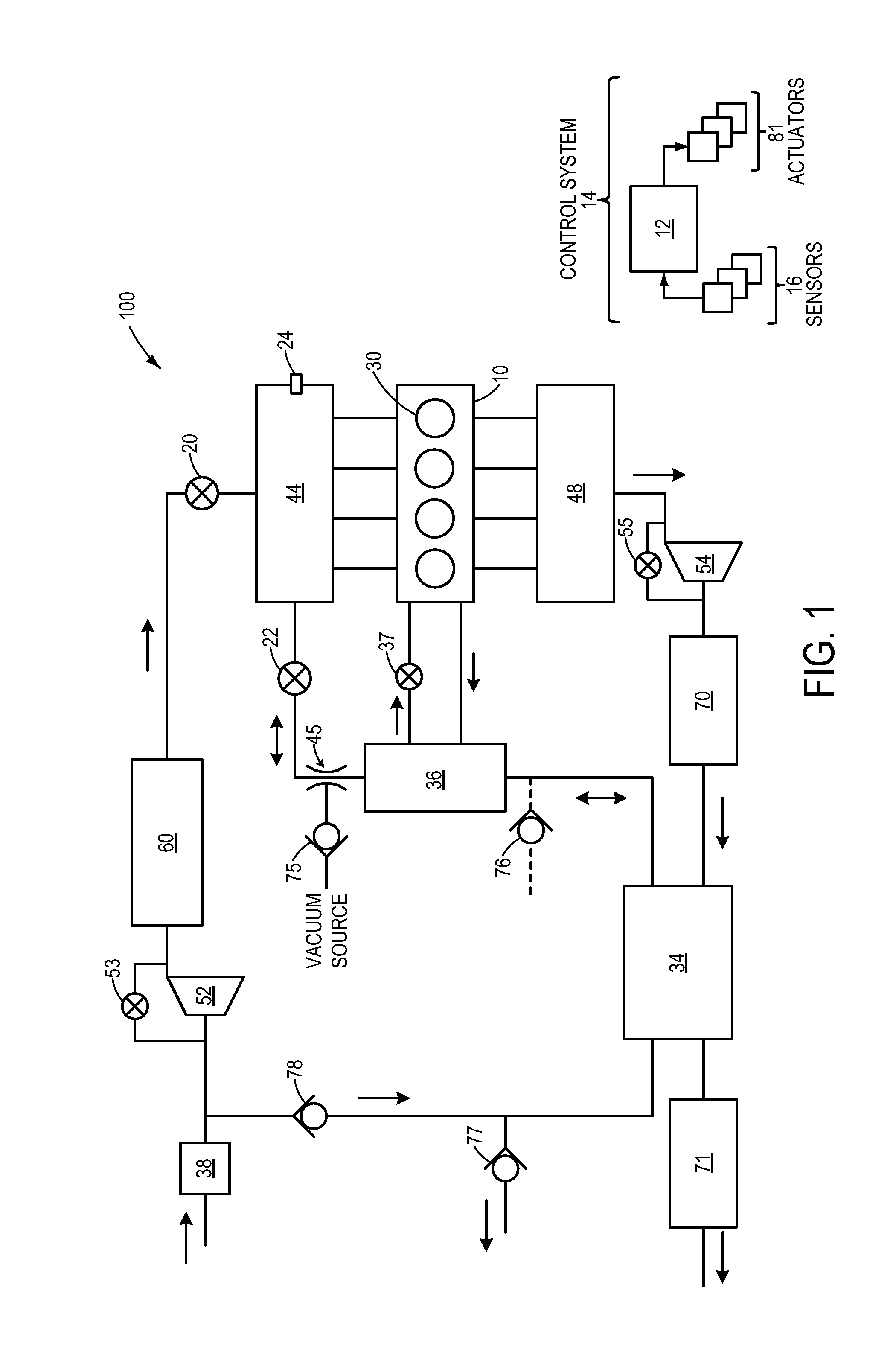
[0012]FIG. 1 shows a schematic diagram of vehicle system 100...


PUM


Abstract

Various systems and method for heating an engine in a vehicle are described. In one example, intake air flowing in a first direction may be heated via a gas-to-gas heat exchange with exhaust gases. The heated intake air may then be used in a subsequent gas-to-liquid heat exchange to heat a fluid circulating through the engine. In another example, intake air flowing in a second direction may be heated via a heat exchange with exhaust gases in order to cool an exhaust catalyst.

Description

TECHNICAL FIELD[0001]The present application relates to heat exchange and, more specifically, to using a heat exchanger for engine heating and exhaust cooling.BACKGROUND AND SUMMARY[0002]Under cold start conditions, an engine has cooled to ambient conditions, which may be relatively hot or cold, and each component of the engine warms-up to a desired operating temperature. During this time, emissions may be higher and there may be energy losses such as viscous energy losses due to a relatively cool temperature of fluids (e.g., engine oil, transmission fluid, etc.) circulating through the powertrain.[0003]Some methods for expediting engine heating include exhaust heat recovery. In some examples, exhaust heat is transferred to engine coolant, for example, via a heat exchanger. Such a method, however, may be only marginally effective in quickly heating the combustion chamber and / or reducing fluid viscosity.[0004]The inventors herein have recognized the above problems and have devised an...

Claims


Application Information

Patent Timeline
Patent Type & Authority Applications(United States)
IPC IPC(8): F02B33/34F02N19/04F02M31/08
CPCF01N5/02F01P3/12F02B33/34F02B37/00F02B37/127F01N13/009F02M31/08Y02T10/144Y02T10/126Y02T10/16F02B47/08F02B37/18F02B37/162Y02T10/12
Inventor ULREY, JOSEPH NORMANPURSIFULL, ROSS DYKSTRALEONE, THOMAS G.
Owner FORD GLOBAL TECH LLC
Why Eureka
Try Eureka