Method of wind tunnel measurement of airfoil

Active Publication Date: 2011-06-16
MITSUBISHI HEAVY IND LTD
View PDF13 Cites 6 Cited by
  • Summary
  • Abstract
  • Description
  • Claims
  • Application Information

AI Technical Summary

Benefits of technology

[0012]Therefore, an object of the present invention is to provide a method of wind tunnel measurement of airfoil, which can measure aerodynamic characteristics of a two-dimensional airfoil section more accurately. Also, another object of the present invention is to provide a method of wind tunnel measurement of airfoil, which can make the flow of the fluid more two-dimensional.
[0014]According to the present invention, it is possible to provide a method of wind tunnel measurement of airfoil, which can measure aerodynamic characteristics of a two-dimensional airfoil section more accurately. Also, according to the present invention, it is possible to provide a method of wind tunnel measurement of airfoil, which can make the flow of the fluid more two-dimensional.

Problems solved by technology

This results in the loss of the lifting power of the airfoil model 111.
Thus, it is difficult to obtain the aerodynamic characteristics of the two-dimensional airfoil section that is originally purposed.

Method used


Image

  • Method of wind tunnel measurement of airfoil
  • Method of wind tunnel measurement of airfoil
  • Method of wind tunnel measurement of airfoil

Examples


Embodiment Construction

[0024]An embodiment of a method of wind tunnel measurement of airfoil according to the present invention will be described below with reference to the attached drawings.

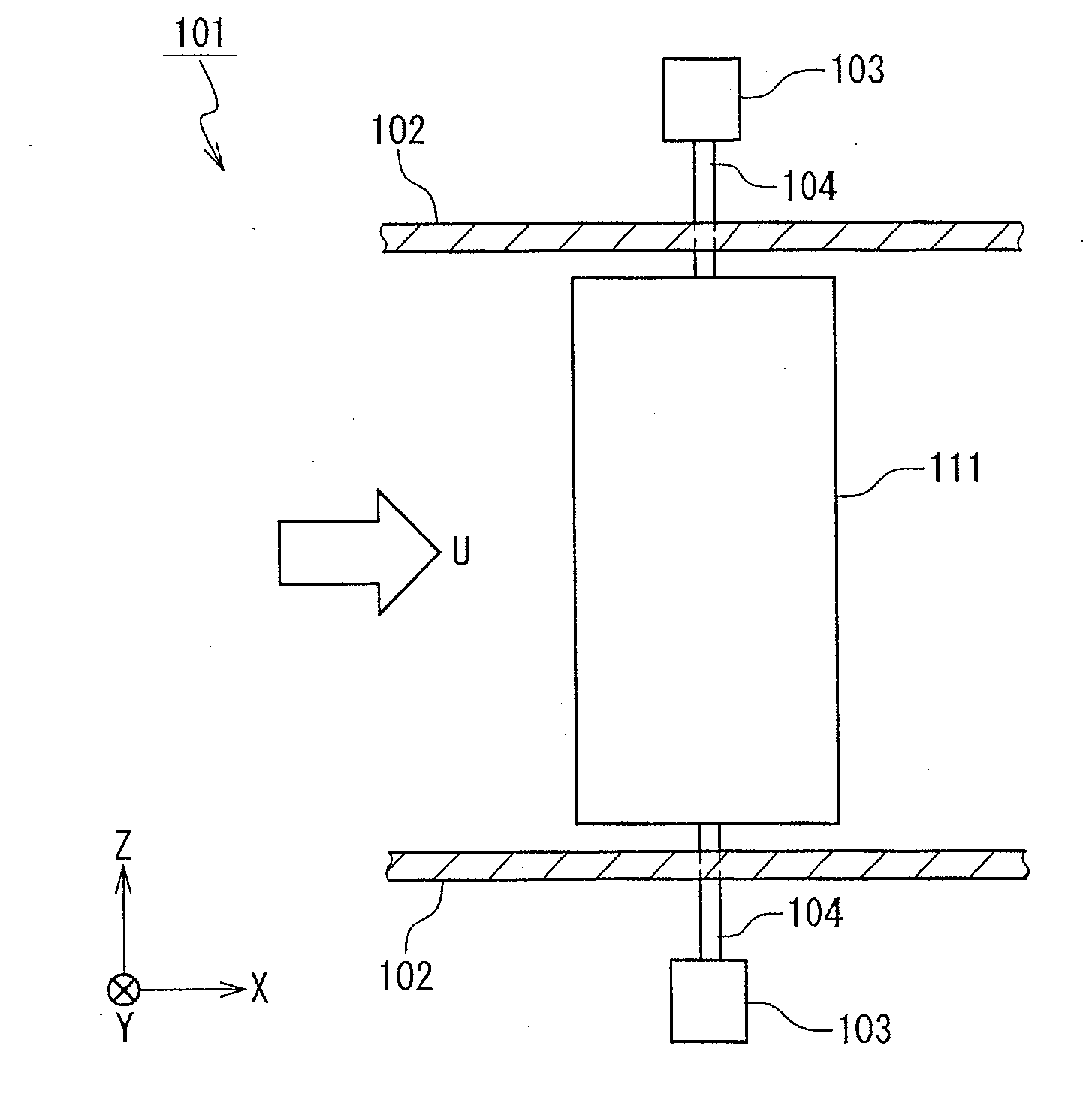
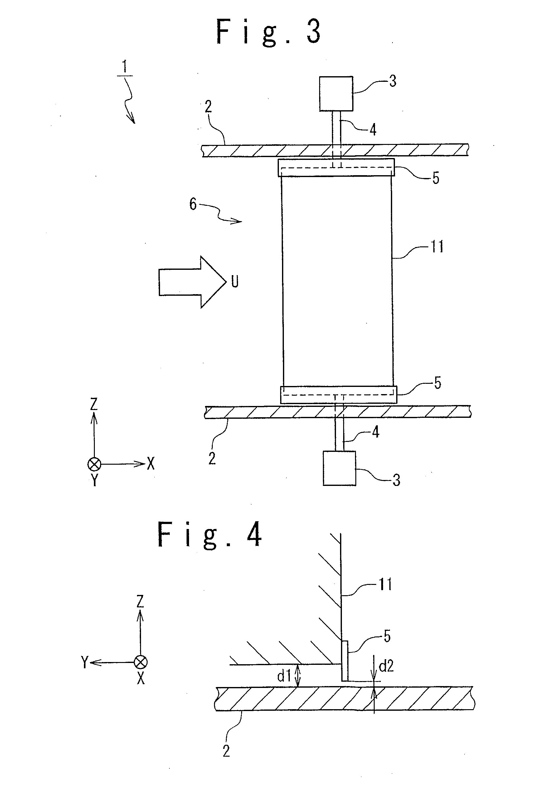
[0025]At first, an airfoil wind tunnel measurement apparatus according to the embodiment of the present invention will be described. FIG. 3 is a schematic view showing an airfoil wind tunnel measurement apparatus according to the embodiment of the present invention. As shown in FIG. 3, a wind tunnel test apparatus 1 includes two walls 2, two supporting members 4 and two load cells 3. Each of the two walls 2 has a flat surface parallel to an x-direction. The two walls 2 are arranged at a predetermined distance from each other in a z-direction. The space between the walls 2 configures a wind tunnel flow path 6. An airfoil (airfoil model 11) under test is arranged in the wind tunnel flow path 6. A fluid (air) for the wind tunnel test flows through the wind tunnel flow path 6. The upper supporting member 4 is arranged to...


PUM


Abstract

A method of wind tunnel measurement of airfoil, includes a step of providing a wind tunnel test apparatus. The wind tunnel test apparatus includes two walls, two supporting members, and two load measuring units. The method further includes steps of: coupling both ends of an airfoil model under test with the two supporting members, respectively; generating a flow of a fluid in the wind tunnel flow path; and measuring a load applied to the airfoil model by using the two load measuring units. A thin film member is stuck on each end of the airfoil model so that a part of the thin film member protrudes from the each end of the airfoil model along an outer circumference throughout an entire circumference. The thin film member has a strength at which the thin film member enables to endure a pressure of the fluid, and is formed of a material which is elastically deformable. The thin film member is provided so that a gap between the each end of the airfoil model and one of the two walls facing to the each end of the airfoil model is blocked.

Description

INCORPORATION BY REFERENCE[0001]This application is based upon and claims the benefit of priority from Japanese patent application No. 2009-280679 filed on Dec. 10, 2009, the disclosure of which is incorporated herein in its entirety by reference.BACKGROUND OF THE INVENTION[0002]1. Field of the Invention[0003]The present invention relates to a method of wind tunnel measurement of airfoil, and more particularly relates to a method of wind tunnel measurement of airfoil, which is used for in a windmill, an aircraft, a turbine and the like.[0004]2. Description of Related Art[0005]As an apparatus that uses a blade, a windmill, an aircraft, a turbine and the like are known. The blade of the windmill, the aircraft or the like is high in aspect ratio (fineness ratio) (e.g., 10 to 20 or more). For this reason, in many cases, the aerodynamic design and the calculation of the aerodynamic performance of the entire blade are carried out by determining the aerodynamic performance of a two-dimensi...

Claims


Application Information

Patent Timeline
IPC IPC(8): G01M9/02
CPCG01M9/062G01M9/04
Inventor KARIKOMI, KAINAKAMURA, YOSUKE
Owner MITSUBISHI HEAVY IND LTD
Why Eureka
Try Eureka