Fuel pump

a technology of fuel pump and jet pump, which is applied in the direction of machines/engines, filtration separation, separation processes, etc., can solve the problems of reducing the discharge amount of the pump device, the vapor generated within the fuel suction filter may not be discharged to an outside of the filter, and the device may decrease the discharge amount, so as to reduce the fuel suction force, reduce the amount of the pump discharge amount of the jet pump, and reduce the effect of the pump discharge amoun

Inactive Publication Date: 2011-06-16
DENSO CORP
View PDF2 Cites 30 Cited by
  • Summary
  • Abstract
  • Description
  • Claims
  • Application Information

AI Technical Summary

Benefits of technology

[0046]When the fuel is emitted from the fuel jet portion, the fuel pressure around the fuel jet portion is decreased, so that the fuel suction force is generated to draw the fuel through the inlet open end. The fuel drawn from the inlet open end is discharged from the outlet open end together with the fuel emitted from the fuel jet portion. When vapors are included in the fuel drawn into the jet pump through the inlet open end, it may become difficult to sufficiently decrease the fuel pressure around the fuel jet portion, to thereby decrease the fuel suction force. Then, the pump discharge amount from the jet pump may be decreased.
[0047]According to the present invention, however, the flow-in of the vapors into the jet pump is effectively suppressed, and thereby the decrease of the pump discharge amount of the jet pump can be effectively suppressed.

Problems solved by technology

As a result, the vapors generated within the fuel suction filter may not be discharged to an outside of the filter and may stay in the filter.
Therefore, the pump device may decrease its discharge amount.
As a result, the pump device may decrease its discharge amount.

Method used


Image

  • Fuel pump
  • Fuel pump
  • Fuel pump

Examples


first embodiment

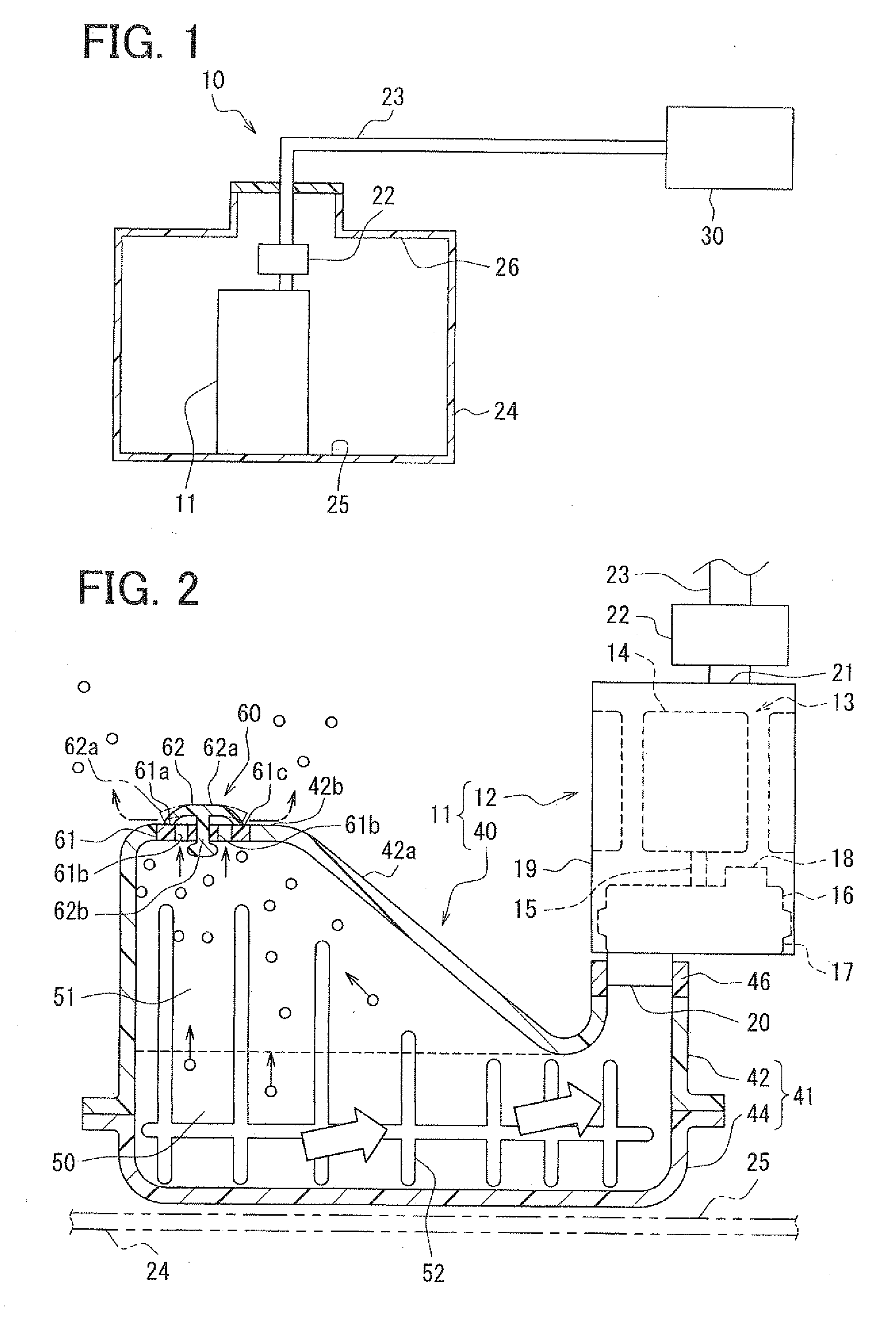
[0064]A first embodiment of the present invention will be explained with reference to the drawings. FIG. 1 is a schematic view showing a fuel supply system 10 incorporating a fuel supply device 11 according to the first embodiment of the present invention.

[0065]In the fuel supply system 10, fuel in a fuel tank 24 is supplied to an engine 30 outside of the fuel tank. The fuel supply system 10 according to the present embodiment is a so-called return fuel supply system, in which surplus fuel which will not be consumed by the engine 30 is treated in an inside of the fuel tank 24 so that the surplus fuel may not be return from the engine 30. The fuel supply system 10 is composed of the fuel supply device 11, a pressure regulating device 22 and a fuel supply pipe 23, and so on.

[0066]The fuel supply device 11 and the pressure regulating device 22 will be explained with reference to FIG. 2. FIG. 2 shows a cross sectional view of the fuel supply device 11. The fuel supply device 11, the pre...

second embodiment

Modification of Second Embodiment

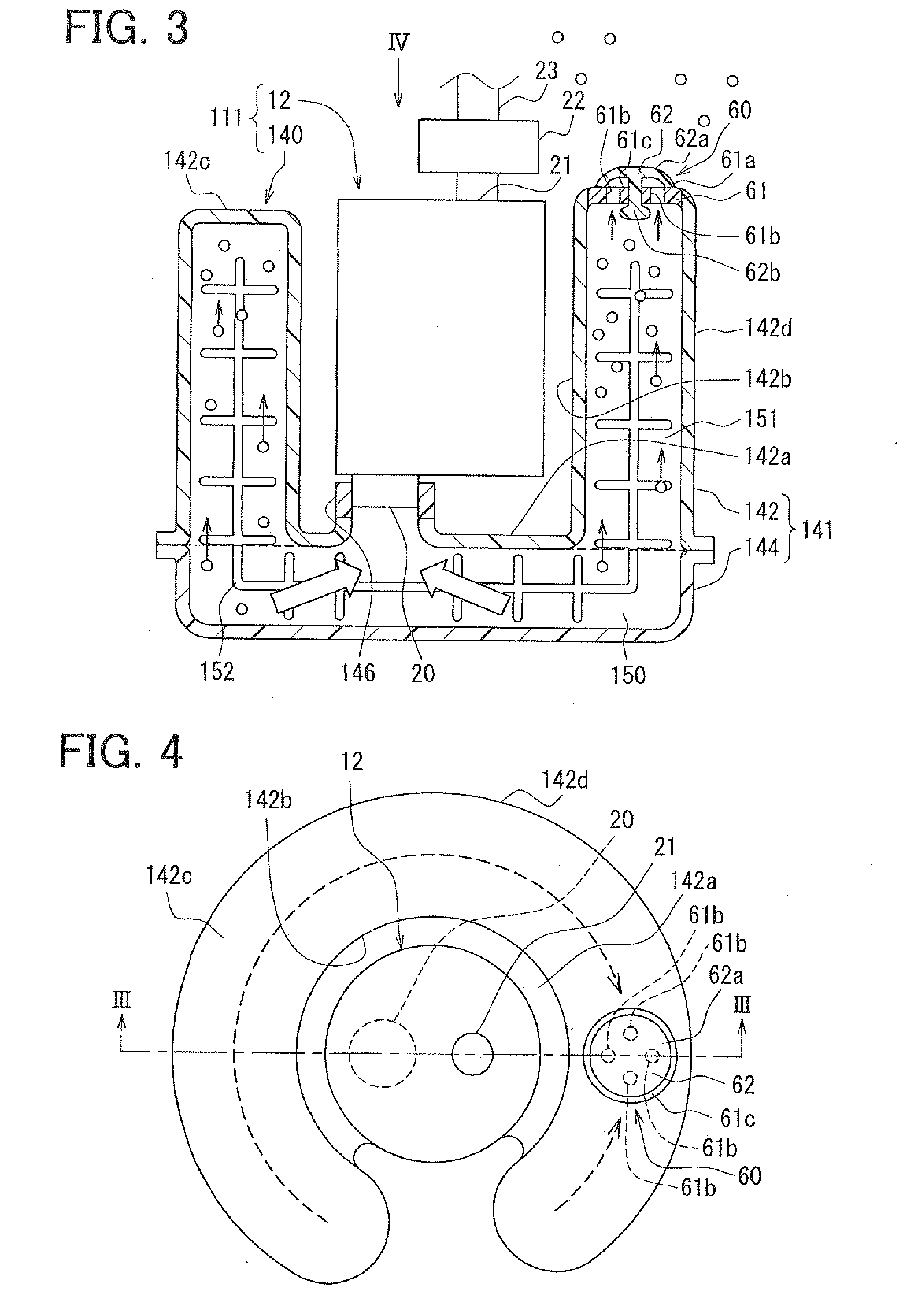
[0120]A modification of the second embodiment will be explained with reference to the drawing. A position for the valve device 60 in the modification is different from the second embodiment. The electric pump 12, the pressure regulating device 22 and the fuel supply pipe 23 are identical to the first embodiment. FIG. 5 is a schematic enlarged cross sectional view showing a filter device 240 of a fuel supply device 211 according to the modification of the second embodiment. The other parts and / or portions, except for a valve device 160 forming a part of the filter device 240, are the same to the second embodiment.

[0121]According to the modification, the valve device 160 is provided at the outer cylindrical wall portion 142d of the first element 142, more exactly, at a portion of the radial side wall portion thereof. Like the valve device 60 of the first embodiment, the valve device 160 of the modification also allows the vapors to flow out from the va...

third embodiment

Modification of Third Embodiment

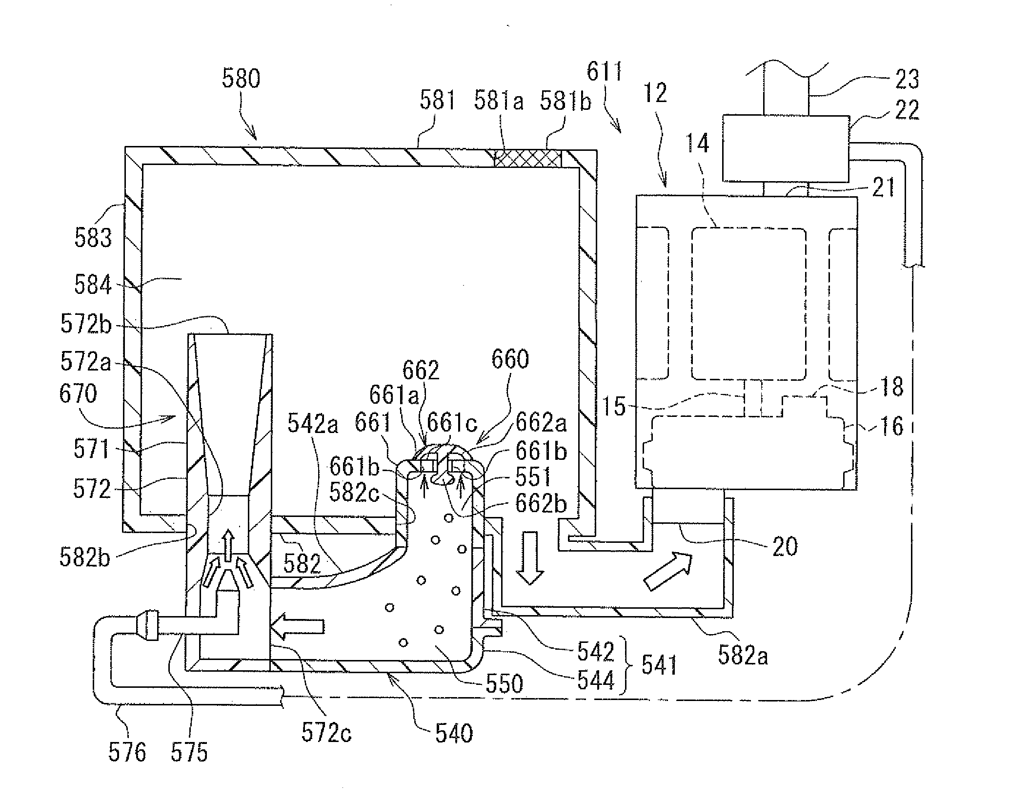
[0138]A modification of the third embodiment will be explained with reference to the drawing. A filter device 440 of the modification is different from the filter device 340 of the third embodiment in that an auxiliary jet pump 470 is provided between the tank portion 340b and the filter portion 340a. The auxiliary jet pump 470 subsidizes fuel supply into the tank portion 340b. The electric pump 12, the pressure regulating device 22 and the fuel supply pipe 23 in this modification are also identical to the first embodiment. FIG. 7 is a schematic cross sectional view showing a fuel supply device 411 according to the modification of the third embodiment. The auxiliary jet pump 470 will be mainly explained.

[0139]The auxiliary jet pump 470 generates fuel suction force and discharges the fuel (sucked from the first fuel passage 350a) into the second fuel passage 350b, in order to subsidize the fuel supply into the tank portion 340b. The auxiliary jet pump ...


PUM

PropertyMeasurementUnit
suction forceaaaaaaaaaa
heightaaaaaaaaaa
areaaaaaaaaaaa

Abstract

A filter device is connected to a fuel pump for supplying filtered fuel to an internal combustion engine. The filter device has a bag-shaped filter element forming therein a fuel passage, wherein fuel passes through the filter element to enter into the fuel passage. The filter element further forms a vapor pooling chamber above the fuel passage, so that vapors separated from the filtered fuel in the fuel passage are moved toward the vapor pooling chamber. A valve device is provided at a portion of the filter device, which is close to the vapor pooling chamber, so that vapors are discharged from the vapor pooling chamber to an outside of the filter device.

Description

CROSS REFERENCE TO RELATED APPLICATION[0001]This application is based on Japanese Patent Application No. 2009-283058 filed on Dec. 14, 2009, the disclosure of which is incorporated herein by reference.FIELD OF THE INVENTION[0002]The present invention relates to a fuel pump for supplying fuel to an internal combustion engine (an engine).BACKGROUND OF THE INVENTION[0003]A fuel pump is known in the art, according to which the fuel pump has a pump device for generating a fuel drawing force for drawing fuel through a suction port and pumping out the fuel from a discharge port, and a filter device for filtering the fuel to be sucked into the pump device.[0004]Generally, when vapors are included in the fuel to be sucked into the pump device through the suction port, the pump device can not discharge the fuel, which at least corresponds to a volume of the vapors. Therefore, a discharge fuel amount of the pump device is decreased when compared with a case in which no vapors are mixed into th...

Claims


Application Information

Patent Timeline
Patent Type & Authority Applications(United States)
IPC IPC(8): F01B31/00
CPCF02M37/025F02M2037/228F02M37/106B01D35/0273B01D35/0276B01D36/001F02M37/50Y10T137/85978
Inventor KAWAJIRI, CHIAKIOKAZONO, TETSUROYAMADA, KATSUHISAMATSUMOTO, NORIYATANAKA, MASAAKI
Owner DENSO CORP
Why Eureka
Try Eureka