Two row bent evaporator

a technology of evaporator and evaporator body, which is applied in the direction of ice removal, stationary conduit assembly, tubular elements, etc., can solve the problems of complex and costly communication manifolds, and achieve the effect of increasing heat transfer

Inactive Publication Date: 2011-06-16
DELPHI TECH INC
View PDF10 Cites 37 Cited by
  • Summary
  • Abstract
  • Description
  • Claims
  • Application Information

AI Technical Summary

Benefits of technology

[0008]One advantage of the invention is that the heat exchanger assembly can be inclined in both horizontal and vertical airflow systems for increasing the heat transfer while also providing positive drainage toward both manifolds. In addition, the vertical juxtaposition of the manifolds provides for a common drainage point of the condensate at the manifolds.
is that the heat exchanger assembly can be inclined in both horizontal and vertical airflow systems for increasing the heat transfer while also providing positive drainage toward both manifolds. In addition, the vertical juxtaposition of the manifolds provides for a common drainage point of the condensate at the manifolds.

Problems solved by technology

However, complex and costly communication manifolds are required to establish fluid communication between the first and second heat exchangers while optimally containing the pressures normally occurring in such systems.

Method used


Image

  • Two row bent evaporator
  • Two row bent evaporator
  • Two row bent evaporator

Examples


Embodiment Construction

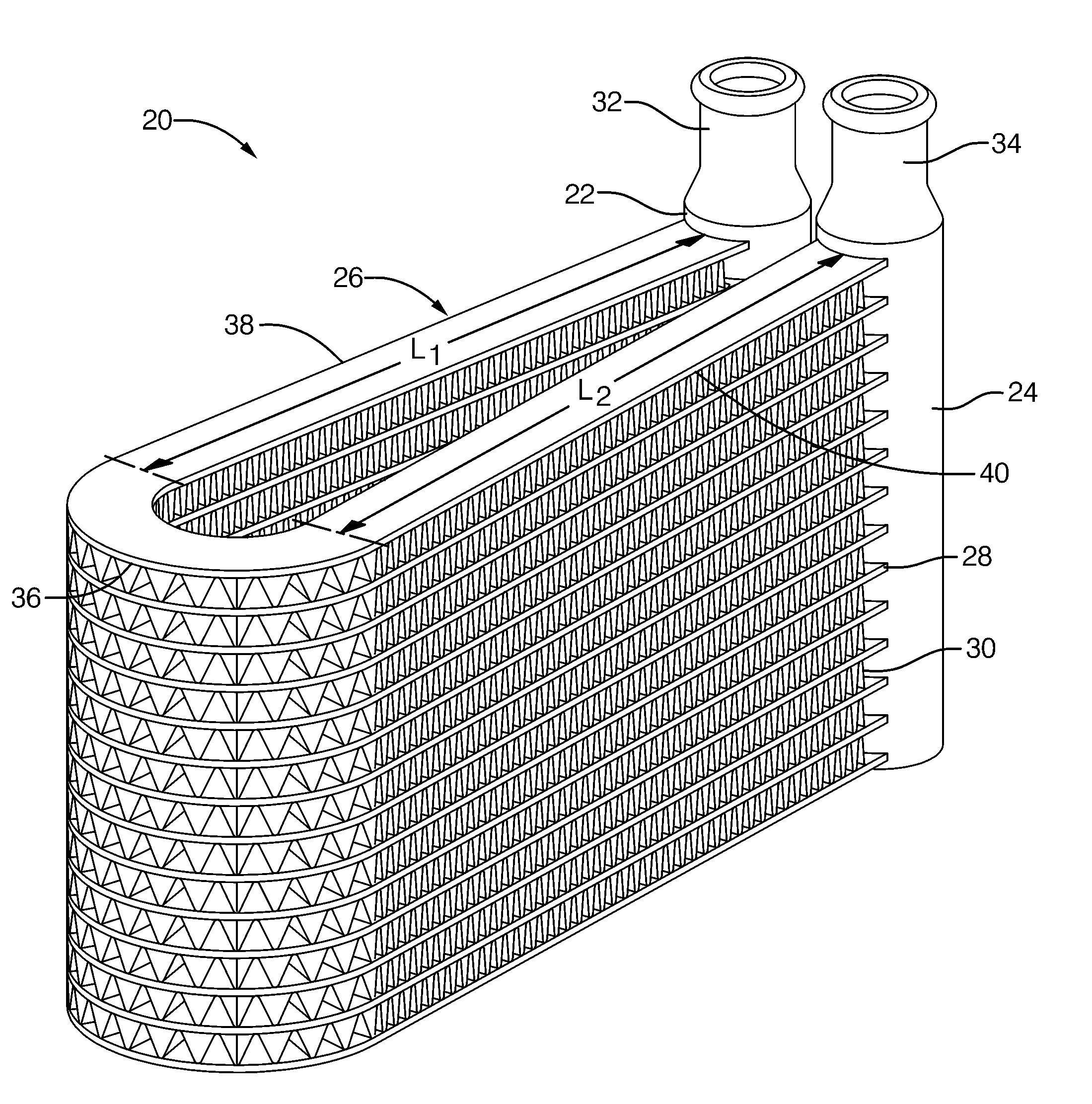
[0013]Referring to the Figures, wherein like numerals indicate corresponding parts throughout the several views, the invention comprises a heat exchanger assembly 20 generally shown including an inlet manifold 22 and an outlet manifold 24 being cylindrical and extending in spaced and parallel relationship to one another. A core 26 extends between the manifolds 22, 24 for conveying a working fluid from the inlet manifold 22 to the outlet manifold 24, and includes a plurality of tubes 28 extending in spaced and parallel relationship to one another between the manifolds 22, 24. The core 26 also includes a plurality of air fins 30 extending back and forth between adjacent ones of the tubes 28 to present a serpentine pattern extending between the adjacent tubes 28. The inlet manifold 22 defines an inlet port 32 for receiving the working fluid, and the outlet manifold 24 defines an outlet port 34 for dispensing the working fluid.

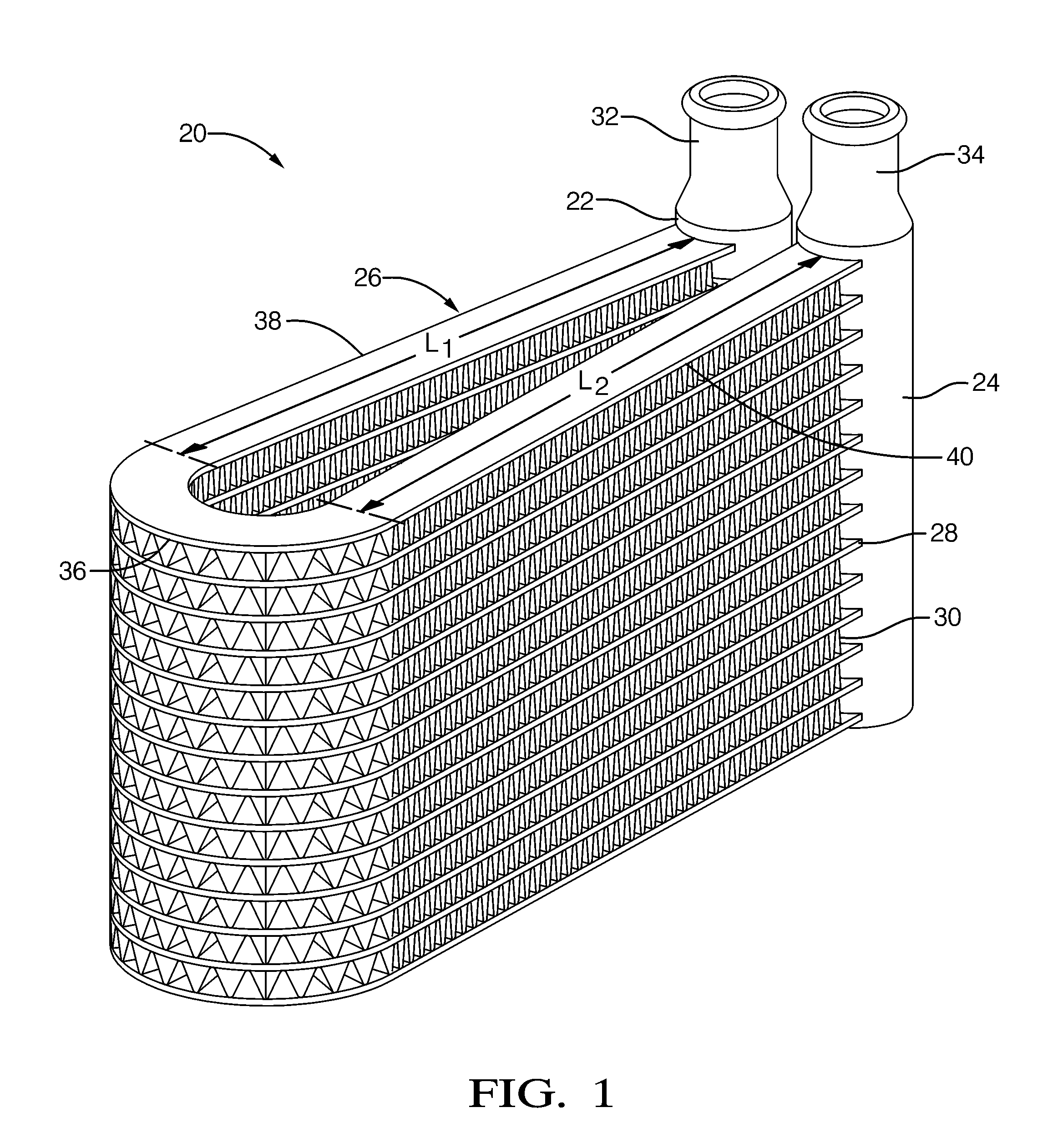
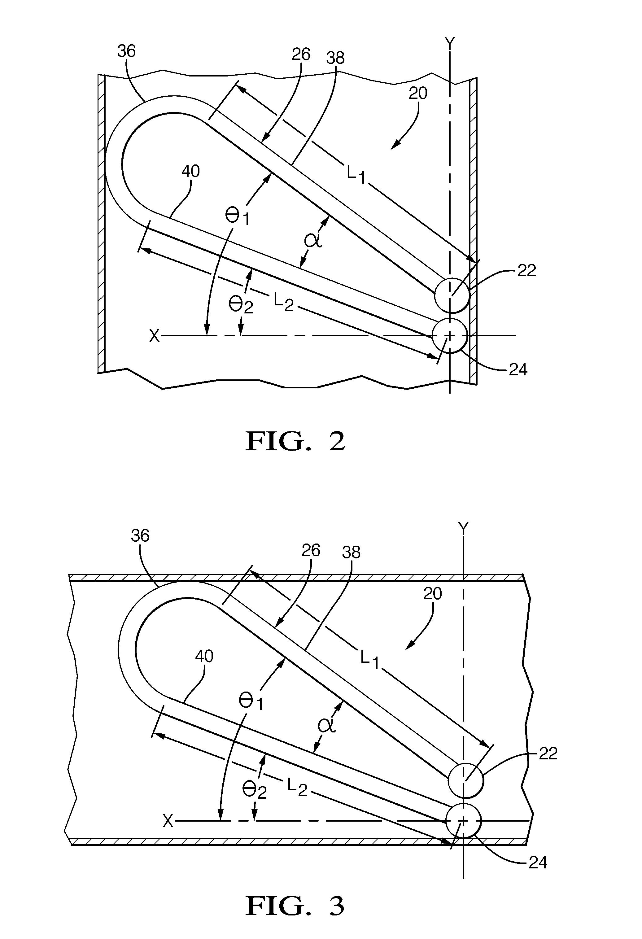
[0014]The core 26 extends through a bend 36 to define a firs...


PUM


Abstract

A core (26) extends through a circular bend (28) greater than 180 degrees to define a first leg (30) between the bend (28) and an inlet manifold (22) and a second leg (32) between the bend (28) and an outlet manifold (24). The legs (30, 32) are disposed in converging relationship from the bend (28) towards the manifolds (22, 24) to define an acute angle (α) between the legs (30, 32). The manifolds (22, 24) are aligned in juxtaposed relationship along an alignment axis (Y) and the legs (30, 32) are disposed in angular relationship to a reference axis (X) to define first and second drainage angles (Θ1, Θ2) between the corresponding legs (30, 32) and the reference axis (X). The second drainage angle (Θ2) is >10 degrees and the first drainage angle is (Θ1)>20 degrees and the acute angle (α) is >10 degrees for draining condensate along the legs (30, 32) toward the juxtaposed manifolds (22, 24) to establish a common drainage point of the condensate.

Description

BACKGROUND OF THE INVENTION[0001]1. Field of the Invention[0002]The subject invention relates to a heat exchanger assembly including a core extending through a bend for greater heat transfer capacity.[0003]2. Description of the Prior Art[0004]The heat exchanger assemblies to which the subject invention pertains are systems which include overlapping or double flows of working fluid to improve performance while minimizing space requirements. The design and manufacture of such a heat exchanger normally includes a first heat exchanger in fluid communication with a second heat exchanger. However, complex and costly communication manifolds are required to establish fluid communication between the first and second heat exchangers while optimally containing the pressures normally occurring in such systems. As a result, it is common to bend the core of a heat exchanger to provide the functionality of a heat exchanger with overlapping or double flows of working fluid while eliminating the com...

Claims


Application Information

Patent Timeline
Patent Type & Authority Applications(United States)
IPC IPC(8): F28F9/02
CPCF28F1/126F28D1/0476F28F17/005
Inventor BEAMER, HENRY E.
Owner DELPHI TECH INC
Why Eureka
Try Eureka