Monitoring fluid movement in a formation

a technology of fluid movement and formation, applied in the direction of survey, wellbore/well accessories, construction, etc., can solve problems such as the degree of water production

Inactive Publication Date: 2011-06-16
SCHLUMBERGER TECH CORP
View PDF44 Cites 27 Cited by
  • Summary
  • Abstract
  • Description
  • Claims
  • Application Information

AI Technical Summary

Problems solved by technology

However, over the lifetime of the well, an increasing percentage of water may enter the zone, thereby eventually resulting in an undesirable degree of water production.

Method used


Image

  • Monitoring fluid movement in a formation
  • Monitoring fluid movement in a formation
  • Monitoring fluid movement in a formation

Examples


Embodiment Construction

[0016]In the following description, numerous details are set forth to provide an understanding of various embodiments of the present invention. However, it will be understood by those skilled in the art that embodiments of the present invention may be practiced without these details and that numerous variations or modifications from the described embodiments are possible.

[0017]As used here, the terms “above” and “below”; “up” and “down”; “upper” and “lower”; “upwardly” and “downwardly”; and other like terms indicating relative positions above or below a given point or element are used in this description to more clearly describe some embodiments of the invention. However, when applied to equipment and methods for use in wells that are deviated or horizontal, such terms may refer to a left to right, right to left, or diagonal relationship as appropriate.

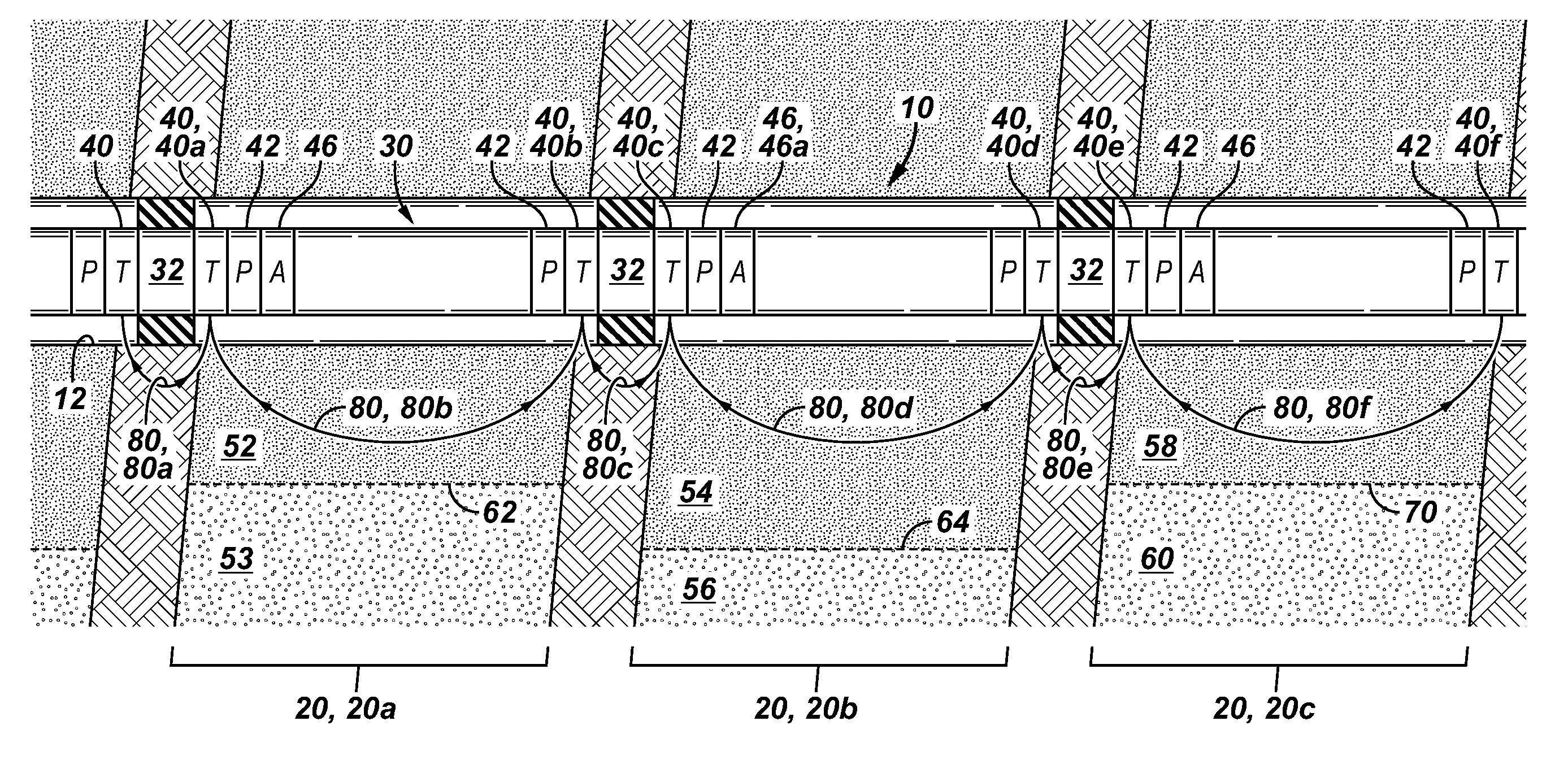
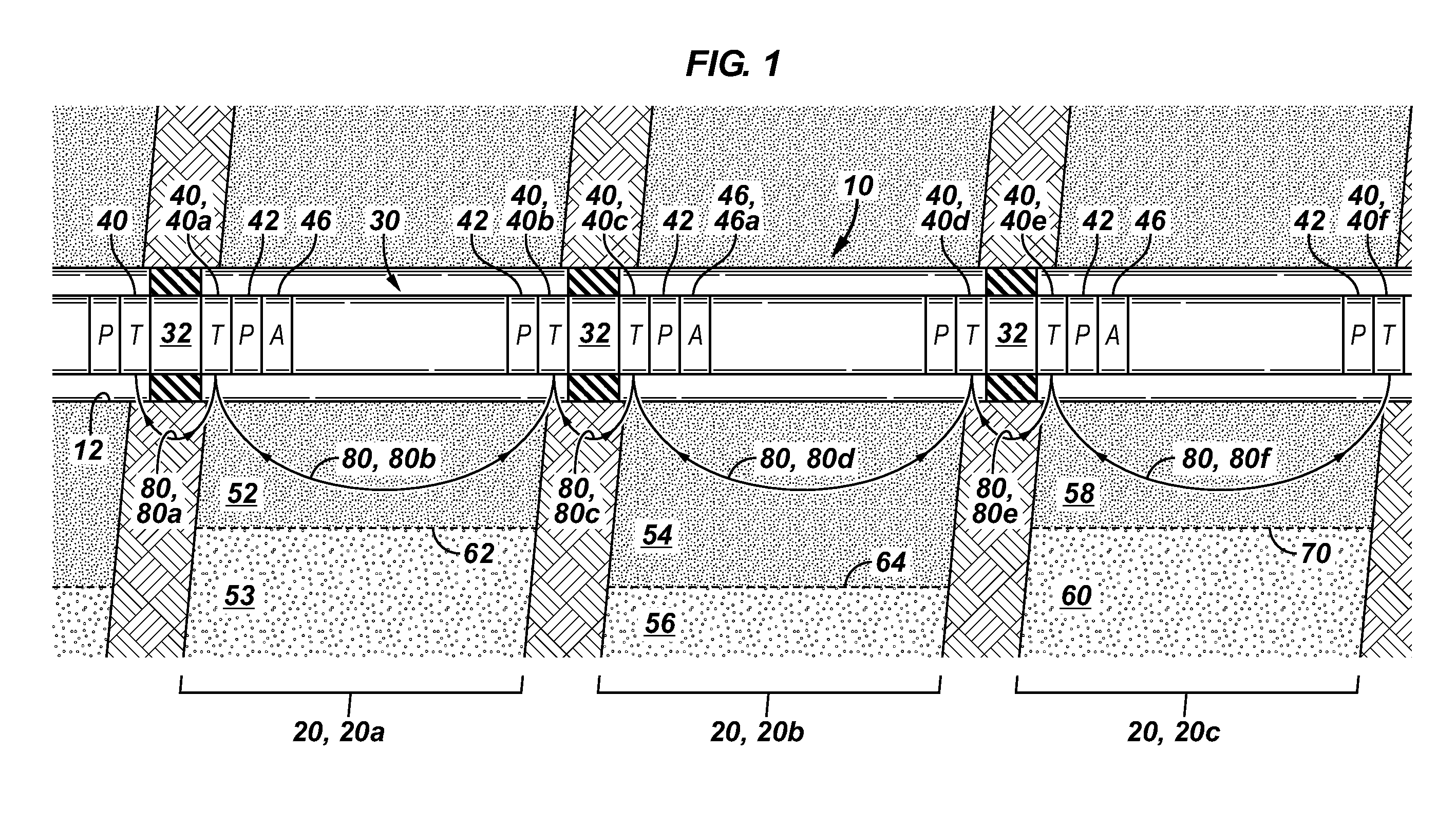
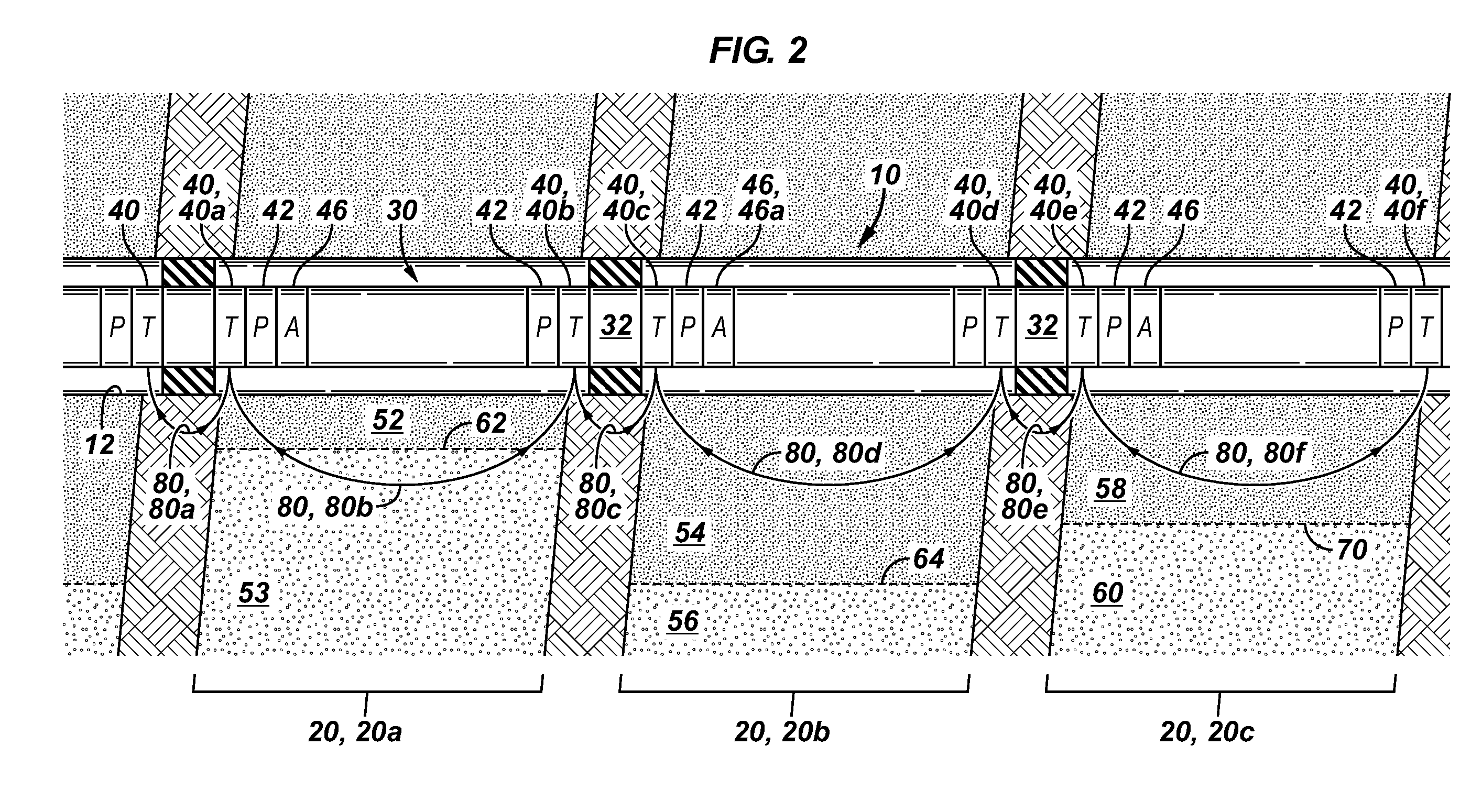
[0018]Techniques and systems are disclosed herein, which take advantage of leakage currents that are generated by downhole wireless ...


PUM


Abstract

A technique includes wirelessly communicating between a first telemetry unit and a second telemetry unit in a well completion. The communicating causes a leakage current between the first and second telemetry units. The technique includes monitoring the leakage current to detect a change in location of a formation fluid layer.

Description

BACKGROUND1. Field of the Invention[0001]The invention generally relates to monitoring fluid movement in a formation.[0002]2. Description of the Related Art[0003]The following descriptions and examples are not admitted to be prior art by virtue of their inclusion in this section.[0004]For purposes of producing a hydrocarbon-based fluid (oil or gas) from a formation, a wellbore typically is drilled into the formation and a well completion is then installed in the wellbore. The well completion generally includes a production tubing string that extends into the wellbore for purposes of communicating the produced well fluid to the surface. The production tubing string may include various downhole tools to control the production of the hydrocarbon-based fluid.[0005]To allow better control over the production, the well may be segmented into isolated production zones so that the production in each zone may be independently controlled. For purposes of establishing isolated production zones,...

Claims


Application Information

Patent Timeline
Patent Type & Authority Applications(United States)
IPC IPC(8): E21B47/00E21B43/00
CPCE21B47/122E21B47/102E21B47/113E21B47/13E21B49/087
Inventor CHEN, KUO-CHIANG
Owner SCHLUMBERGER TECH CORP
Why Eureka
Try Eureka