
Apparatus and Method for Reaming a Wellbore During the Installation of a Tubular String

a tubular string and wellbore technology, applied in the direction of shaft sinking, shaft equipment, borehole/well accessories, etc., can solve the problems of reducing the torque capacity of the drilling rig, the liner thread or both, and the inability to work the liner string to the bottom of the wellbore, so as to reduce the weight applied

Active Publication Date: 2011-06-16
HALLIBURTON ENERGY SERVICES INC
View PDF8 Cites 10 Cited by
  • Summary
  • Abstract
  • Description
  • Claims
  • Application Information

AI Technical Summary

Benefits of technology

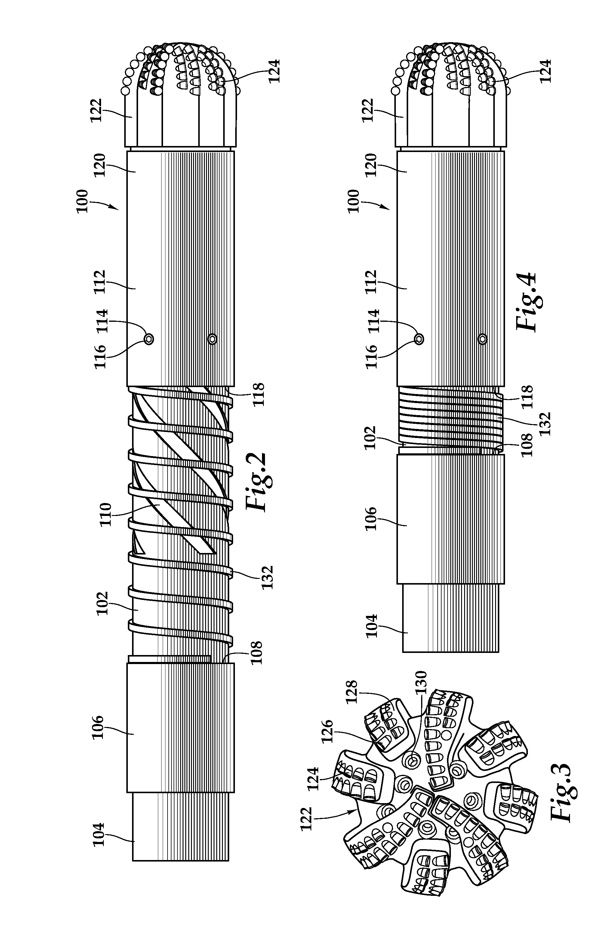
[0012]In another aspect, the present invention is directed to a method for reaming a wellbore. The method includes coupling a reamer assembly to a tubular string, the reamer assembly includes a mandrel, a sleeve operably associated with the mandrel and a reamer shoe coupled to the sleeve, running the tubular string into the wellbore until the reamer shoe contacts a restriction in the wellbore, applying weight on the reamer shoe via the tubular string, longitudinally contracting the reamer assembly to rotate the sleeve relative to the mandrel, thereby rotating the reamer shoe, reducing the weight applied to the reamer shoe and longitudinally extending the reamer assembly.

Problems solved by technology

It has been found, however, that in certain wellbores such as deviated wellbores, horizontal wellbores, multilateral wellbores and the like, it is difficult to work the liner string to the bottom of the wellbore.
For example, during drilling of the lowermost section of the wellbore and the installation of the liner string, debris may build up near the bottom of the wellbore, which prevents installation of the liner string at the desired depth.
It has been found, however, that in certain deep wells including the aforementioned deviated wellbores, horizontal wellbores, multilateral wellbores and the like, the torque capacity of the drilling rig, the liner threads or both, limits the ability to rotate the liner string.

Method used


Image

  • Apparatus and Method for Reaming a Wellbore During the Installation of a Tubular String
  • Apparatus and Method for Reaming a Wellbore During the Installation of a Tubular String
  • Apparatus and Method for Reaming a Wellbore During the Installation of a Tubular String

Examples


Embodiment Construction

[0024]While the making and using of various embodiments of the present invention are discussed in detail below, it should be appreciated that the present invention provides many applicable inventive concepts, which can be embodied in a wide variety of specific contexts. The specific embodiments discussed herein are merely illustrative of specific ways to make and use the invention, and do not delimit the scope of the invention.

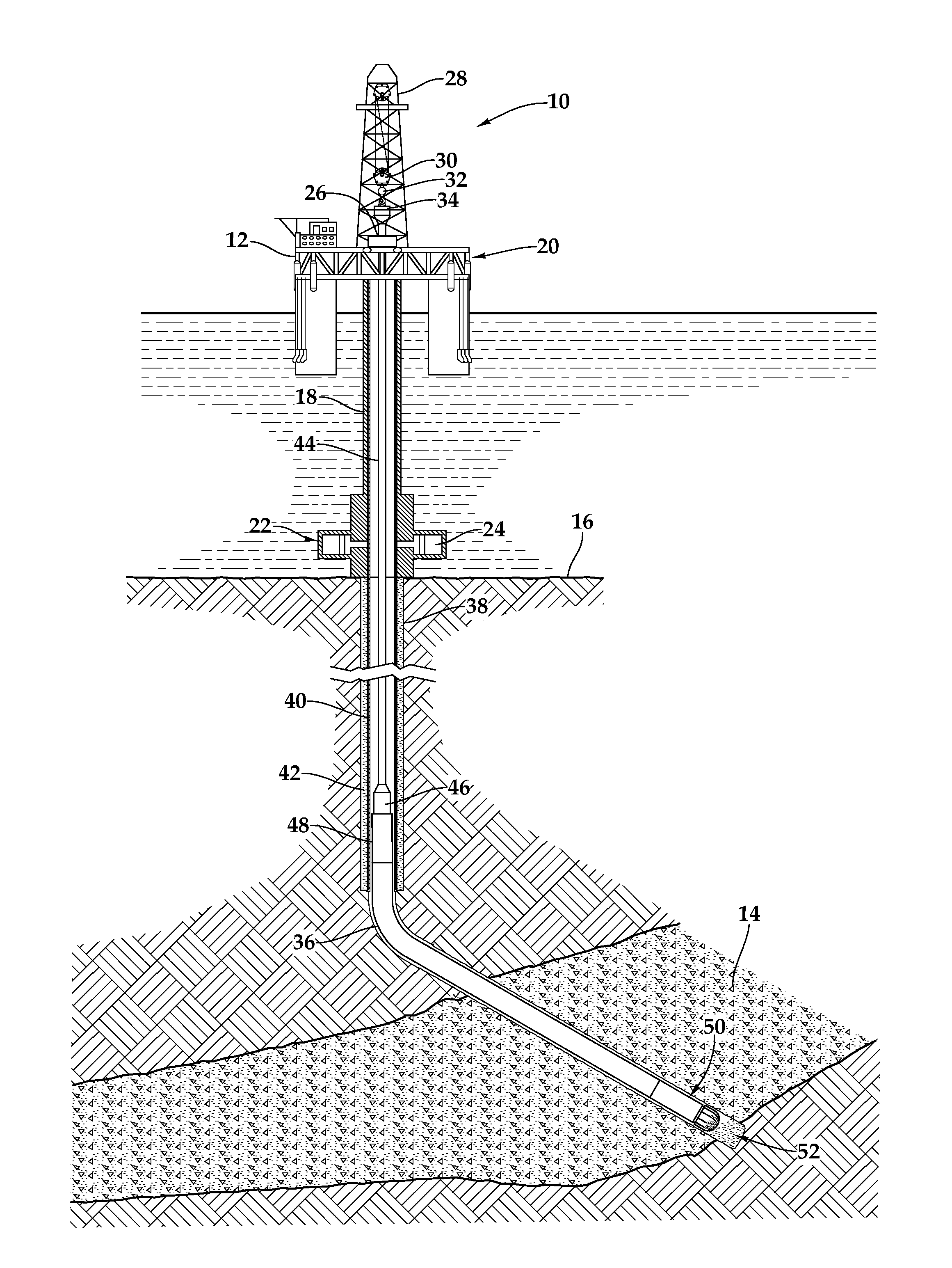
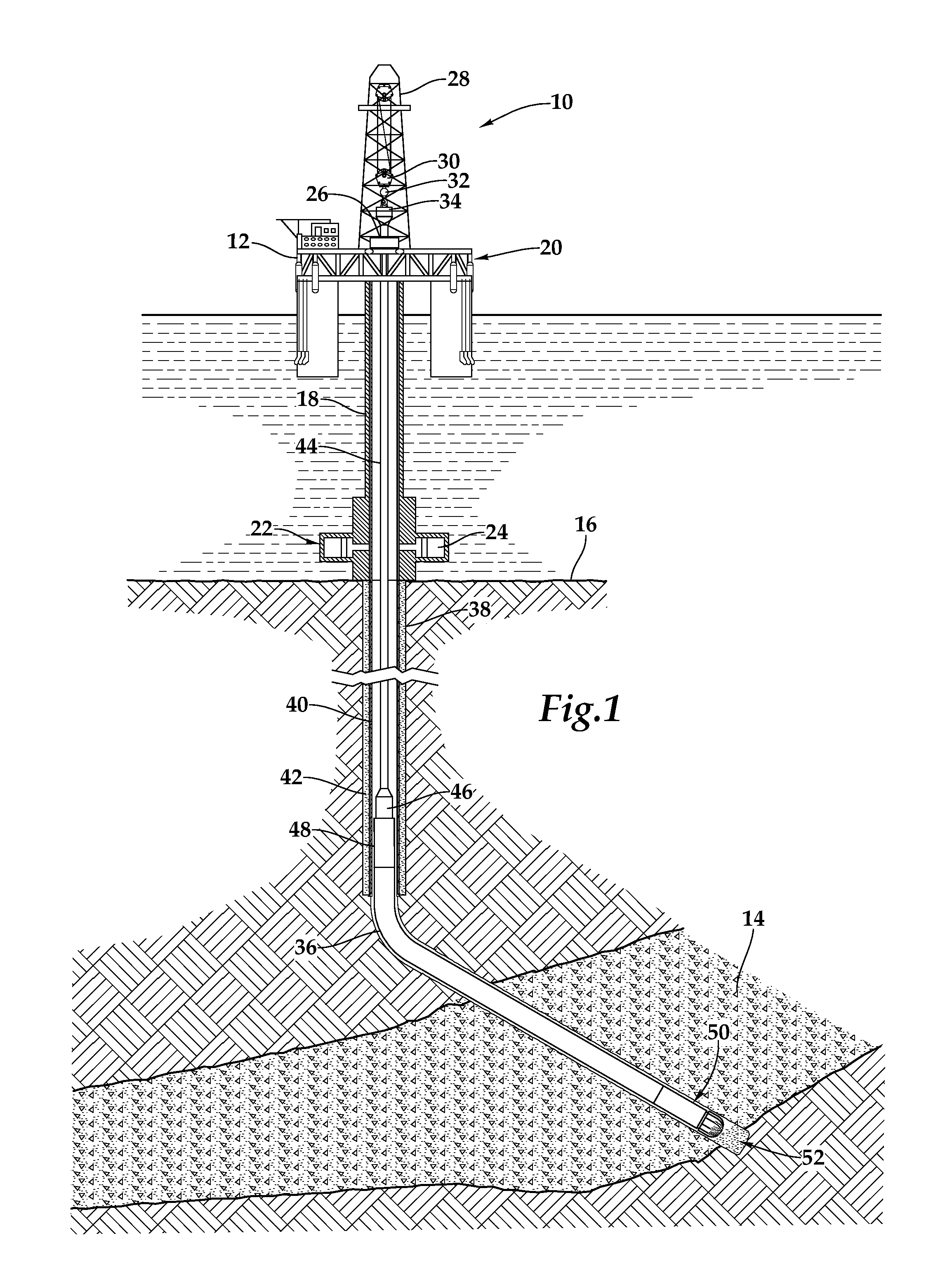
[0025]Referring initially to FIG. 1, an apparatus for reaming a wellbore being deployed from an offshore platform is schematically illustrated and generally designated 10. A semi-submersible platform 12 is centered over submerged oil and gas formation 14 located below sea floor 16. A subsea conduit 18 extends from deck 20 of platform 12 to wellhead installation 22, including blowout preventers 24. Platform 12 has a hoisting apparatus 26, a derrick 28, a travel block 30, a hook 32 and a swivel 34 for raising and lowering pipe strings, such as a liner string 36....


PUM


Abstract

An apparatus for reaming a wellbore without rotating a tubular string that is extendable to a surface. A mandrel (102) is coupled to a downhole end of the tubular string. The mandrel (102) has at least one groove (110) in a sidewall portion thereof. A sleeve (112) is operably associated with the mandrel (102) such that longitudinal travel of the mandrel (102) relative to the sleeve (112) shifts the sleeve (112) between extended and contracted positions relative to the mandrel (102). A reamer shoe (122) is coupled to a downhole end of the sleeve (112). At least one coupling device (116) is operably associated with the sleeve (112) and extendable into the at least one groove (110) such that longitudinal travel of the mandrel (102) relative to the sleeve (112) caused the sleeve (112) to rotate relative to the mandrel (102), thereby rotating the reamer shoe (122).

Description

FIELD OF THE INVENTION[0001]This invention relates, in general, to equipment utilized in conjunction with operations performed in subterranean wells and, in particular, to an apparatus and method for reaming a wellbore during the installation of a tubular string without rotating the tubular string.BACKGROUND OF THE INVENTION[0002]Without limiting the scope of the present invention, its background is described with reference to constructing a subterranean well including a liner string, as an example.[0003]In conventional practice, the drilling of an oil or gas well involves creating a wellbore that traverses numerous subterranean formations. For a variety reasons, each of the formations through which the well passes is preferably sealed. For example, it is important to avoid an undesirable passage of formation fluids, gases or materials out of the formation and into the wellbore or for wellbore fluids to enter the formation. In addition, it is commonly desired to isolate producing fo...

Claims


Application Information

Patent Timeline
Patent Type & Authority Applications(United States)
IPC IPC(8): E21D1/06E21B17/14
CPCE21B10/26E21B17/076E21B17/073
Inventor DECLUTE-MELANCON, DANIEL
Owner HALLIBURTON ENERGY SERVICES INC
Learn More