
Magnetic mass-lift impulsive seismic energy source including repelling electromagnets and reaction mass damping

a technology of reaction mass damping and magnetic mass lift, which is applied in seismic energy generation, seismicology, instruments, etc., can solve the problem of limiting the timing accuracy of seismic impulses generated by the source, the inverse relationship of the magnetizing attraction between the electromagnet and the top block,

Inactive Publication Date: 2011-06-16
PGS ONSHORE INC
View PDF10 Cites 11 Cited by
  • Summary
  • Abstract
  • Description
  • Claims
  • Application Information

AI Technical Summary

Benefits of technology

[0011]A method for seismic surveying according to another aspect of the invention includes actuating a first electromagnet associated with a reaction mass and a second electromagnet associated with a base plate in contact with a ground surface so as to cause the reaction mass to lift away from the base plate. The first electromagnet and the second electromagnet are deactivated such that gravity draws the reaction mass toward the base plate. Motion of the reaction mass toward the base plate is damped sufficiently to substantially prevent generation of an impulse when the reaction mass contacts the base plate.

Problems solved by technology

A limitation to the foregoing type of mass lift impulsive seismic source known in the art is that the magnetic attractive force between the electromagnet and the top block is inversely related to the distance between them.
Since no force can be transmitted to the ground once the attracting surfaces of the moving mass and top block meet, the above distance limitation will impose an absolute limit on the active stroke of the device, and thus the maximum attainable ground movement caused by the base plate.
Further, because the attractive force between electromagnet and top block increases as the distance therebetween is reduced, the movable mass tends to accelerate during its travel toward the top block, limiting the accuracy of timing of seismic impulses generated by the source.

Method used


Image

  • Magnetic mass-lift impulsive seismic energy source including repelling electromagnets and reaction mass damping
  • Magnetic mass-lift impulsive seismic energy source including repelling electromagnets and reaction mass damping
  • Magnetic mass-lift impulsive seismic energy source including repelling electromagnets and reaction mass damping

Examples


Embodiment Construction

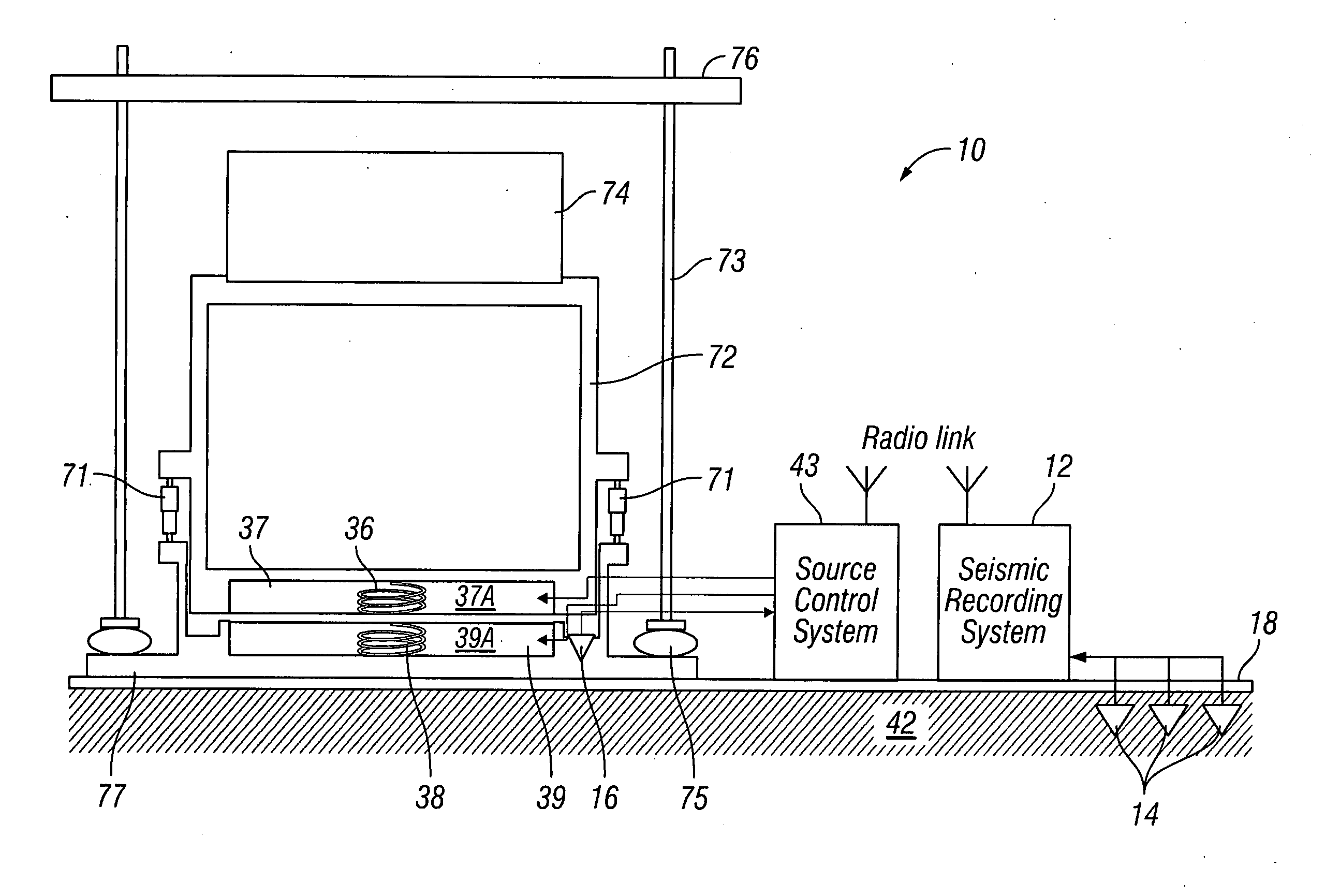
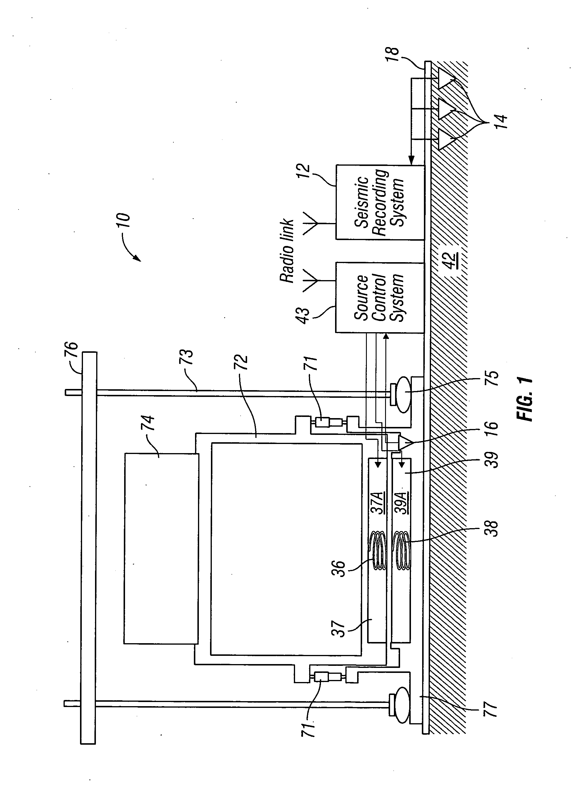
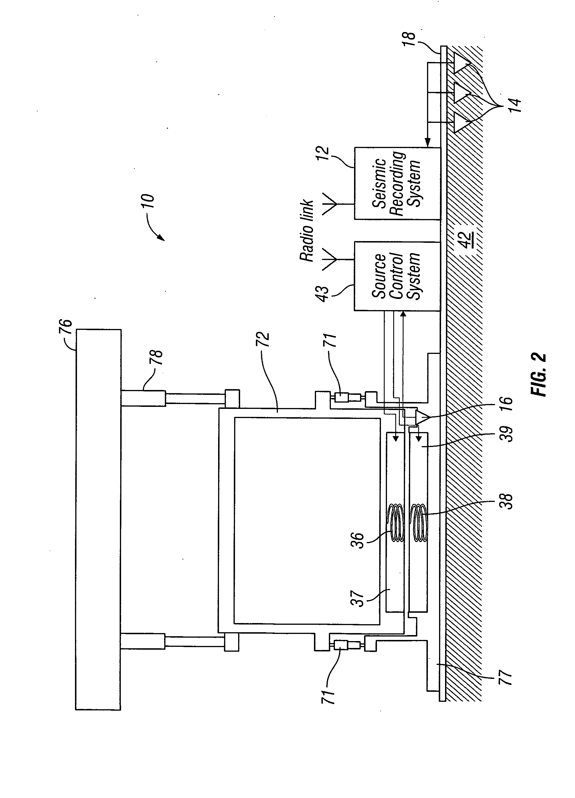
[0015]An example seismic acquisition system including a mass lift seismic energy source according to the invention is shown schematically in FIG. 1. The source 10 is disposed at a selected position on the Earth's surface 18 (or in a body of water) above subsurface rock formations 42 to be evaluated. A plurality of seismic receivers 14 such as geophones, hydrophones or accelerometers may be disposed at spaced apart locations on the surface, in the body of water or on the bottom of the body of water above the subsurface rock formations 42. The receivers 14 generate electrical and / or optical signals in response to seismic energy detected from the subsurface formations 42. The signals generated by the receivers 14 may be conducted to a recording system 12. The recording system may include devices (not shown separately) for making a time indexed record of the signals detected by the receivers 14. The recording time is typically indexed to the actuation time of the seismic energy source 1...


PUM


Abstract

A seismic energy source includes a base plate having a first electromagnet thereon. A reaction mass has a second electromagnet thereon. A switchable current source is connected to the first and second electromagnets such that the first electromagnet repels the second electromagnet. At least one damper is functionally connected between the reaction mass and the base plate. The damper is configured to enable faster movement of the reaction mass away from the base plate than toward the base plate.

Description

CROSS-REFERENCE TO RELATED APPLICATIONS[0001]Not applicable.STATEMENT REGARDING FEDERALLY SPONSORED RESEARCH OR DEVELOPMENT[0002]Not applicable.BACKGROUND OF THE INVENTION[0003]1. Field of the Invention[0004]The invention relates generally to the field of seismic energy sources. More particularly, the invention relates to impulsive seismic energy sources using electromagnets to move a mass.[0005]2. Background Art[0006]Seismic surveying includes imparting seismic energy from a seismic energy source into rock formations below the land surface, or below the bottom of a body of water in marine environments. The seismic energy travels from the source, through the rock formations and is reflected from acoustic impedance boundaries in the subsurface. Such acoustic impedance boundaries are typically at the interfaces of layers of different rock formations. The reflected seismic energy is detected by a plurality of seismic receivers disposed at the surface, on the water bottom or in the wate...

Claims


Application Information

Patent Timeline
Patent Type & Authority Applications(United States)
IPC IPC(8): G01V1/04
CPCG01V1/147
Inventor GREIG, MALCOLM JOHN
Owner PGS ONSHORE INC
Learn More