Ion optics

Inactive Publication Date: 2001-06-12
KAUFMAN & ROBINSON
View PDF2 Cites 12 Cited by
  • Summary
  • Abstract
  • Description
  • Claims
  • Application Information

AI Technical Summary

Benefits of technology

In light of the foregoing, it is an overall general object of the invention to provide an improved ion optics design that greatly reduces the forces on insulator seats incorporated into ion optics grids and thereby reduces the associated plastic deformation that degrades the alignment precision of apertures through which the ions are accelerated.
Another object of the present invention is to provide a design in which the elastic motion of parts is sufficient to maintain the positive contact of insulators with adjacent parts and thereby prevent the gradual rotation of insulators during repeated thermal cycles and the eventual shorting of the ion optics due to that rotation.
A further object of the present invention is to provide a design that is more adaptable to ion optics configurations having more than two grids.

Problems solved by technology

Variations in temperature during ion source operation will tend to cause further departures from the ideal.
This practical improvement reduces but does not eliminate the plastic deformation in the contact region.
A related problem encountered with the prior art is the rotation of insulators.
At some point in a startup, operation, and shutdown thermal cycle, positive contact can be lost between a spherical insulator and adjacent parts.
However, when the spherical insulator rotates far enough, the sputter deposits on it can move from a relatively benign location to one that causes electrical shorting between the grids, thereby terminating normal operation.
With the substantial relative thermal expansion that takes place and the stiffness required to assure flatness for the support members 56 and 58, the rotation of insulators has been a recurring problem.

Method used


Image

  • Ion optics
  • Ion optics
  • Ion optics

Examples


Embodiment Construction

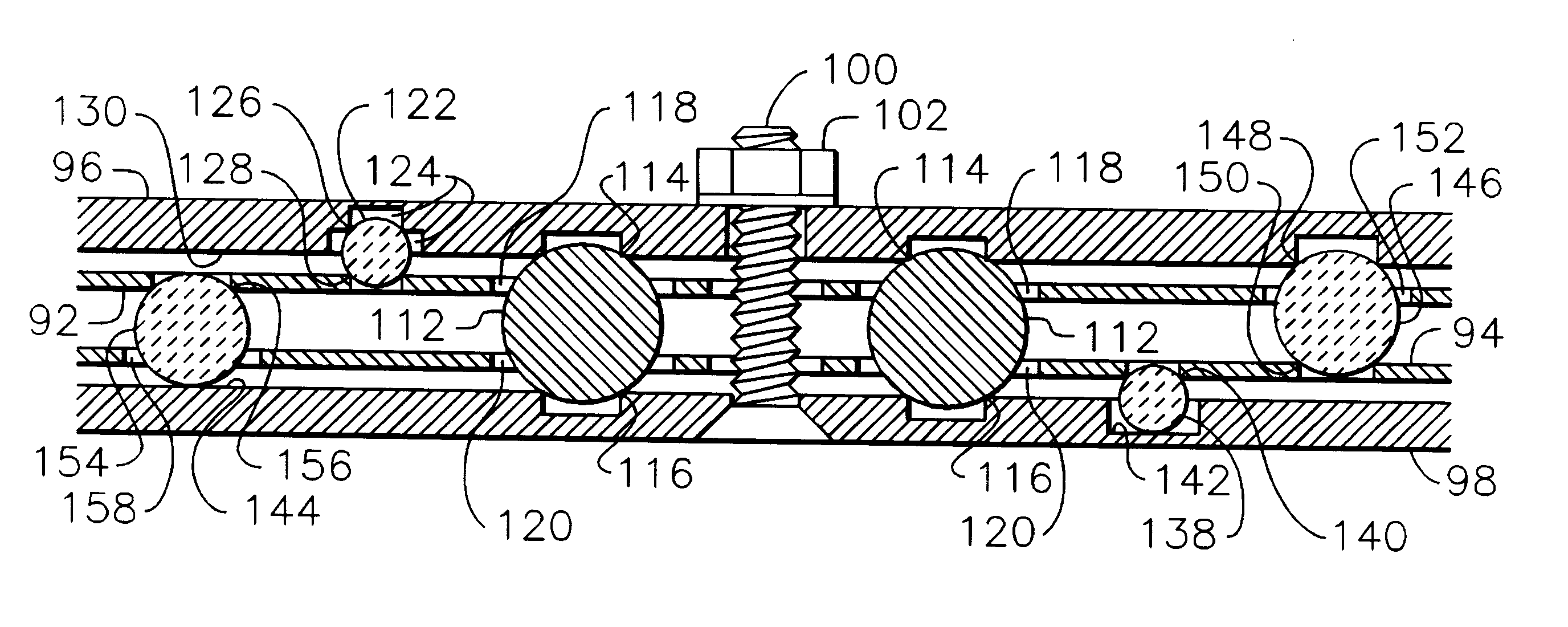
Referring to FIG. 9, there is shown ion optics 90 constructed in accordance with a specific embodiment of the present invention. In FIG. 10 is shown an enlarged schematic cross-sectional view of the ion optics of FIG. 9 along section A--A therein. This view shows the apertured regions of grids 92 and 94 through which the ions are accelerated as well as the surrounding peripheral regions where the grids are supported and held in alignment. Ion optics 90 includes a first grid 92, a second grid 94, a first support member 96, a second support member 98 screws 100, and nuts 102. The screws and nuts hold the ion optics together. Grids 92 and 94 are separated from support members 96 and 98, both by spaces 104 and 106 and by clearance holes 108 and 110 for screws 100 in grids 92 and 94. This separation permits grids 92 and 94 to be electrically isolated from support members 96 and 98, as well as from each other.

FIG. 11 shows an enlarged schematic cross-sectional view of the ion optics of FI...


PUM


Abstract

In one embodiment of the present invention, the ion optics for use with an ion source have first and second electrically conductive grids having mutually aligned respective pluralities of apertures through which ions may be accelerated and wherein each has an integral peripheral portion. There is also a support member. There are first and second series of seats around the respective peripheral portions of the first and second grids. A plurality of first spherical insulators are distributed between seats of the first and second series, thereby establishing a predetermined distance between the grids while still enabling radial movement between their peripheral portions. There are third and fourth series of seats around the support member and the peripheral portion of the second grid, respectively, with seats of the fourth series displaced from those of the second series in the same grid. A plurality of second spherical insulators are distributed between seats of the third and fourth series, thereby establishing a predetermined distance between the support member and the second grid while still enabling motion in at least the radial direction between the support member and the peripheral portion of the second grid. A clamping force between the support member and the peripheral portion of the first grid maintains contact between the insulators and their seats.

Description

FIELD OF INVENTIONThis invention relates generally to gridded ion sources, and more particularly to the design of ion optics for such ion sources.This invention can find application in a variety of thin film applications such as etching, sputter deposition, or the property modification of deposited films. It can also find application in space propulsion.BACKGROUND ARTGridded ion sources are described in an article by Kaufman, et al., in the AIAA Journal, Vol. 20 (1982), beginning on page 745, which is incorporated herein by reference. The ion sources described therein use a direct-current discharge to generate ions. It is also possible to use a radiofrequency discharge to generate ions, as shown by U.S. Pat. No. 5,274,306--Kaufman et al.Typical ion optics for gridded ion sources are also described in the aforesaid article by Kaufman, et al. An improved ion optics design is described in U.S. Pat. No. 4,873,467--Kaufman, et al., which as incorporated herein by reference. The problems ...

Claims


Application Information

Patent Timeline
IPC IPC(8): F02K11/00H01J27/02F02K99/00
CPCH01J27/022
Inventor KAHN, JAMES R.KAUFMAN, HAROLD R.ROBINSON, RAYMOND S.
Owner KAUFMAN & ROBINSON
Why Eureka
Try Eureka