Micromanipulator including piezoelectric benders

a micromanipulator and piezoelectric technology, applied in the field of micromanipulators, can solve the problems of unsatisfactory reliability, inability to provide integral units sufficiently compact in terms of operation of several appliances, and inability to exploit this particular type of solution with a sufficient reliability in highly precise procedures, etc., to achieve the effect of improving work productivity, simple construction and optimally small spa

Inactive Publication Date: 2006-11-28
CHIP MAN TECH
View PDF12 Cites 11 Cited by
  • Summary
  • Abstract
  • Description
  • Claims
  • Application Information

AI Technical Summary

Benefits of technology

[0008]The most important benefits gained by a micromanipulator of the invention include the simplicity of its operating principle and constructions applicable thereto, especially by virtue of an optimally small space required by one or preferably several piezoelectric benders exploited in the invention, the axial direction of motion for the micromanipulator being especially implementable at a sufficient motion frequency / accuracy by means of a linear motor located on the same longitudinal axis as the piezoelectric bender. The piezoelectric bender used in a micromanipulator of the invention comprises in its most favorable embodiment a bi- or multimorph cantilever structure, which further enables an extremely simple construction, wherein each direction of motion is implementable by means of benders connected successively to each other on a common longitudinal axis and located in planes perpendicular to each other. Thus, by virtue of an elongated micromanipulator structure of the invention, it is possible to accommodate a sufficient number of micromanipulators for use e.g. in a microscope application, such that all media and operating instruments needed in a presently relevant process are prefit and ready in position in each micromanipulator previously focused in radial direction on an operating target. Hence, in this respect, a significant improvement is first of all attainable in the discussed type of work by avoiding all futile dismounting, cleaning and refitting operations. This means a marked improvement in productivity of work, resulting in a continuously proceeding operation to establish a comprehensively optimal operation by avoiding unnecessary standing times and delays.
[0009]Another essential benefit gained by a micromanipulator of the invention lies in the fact that it does not necessarily require precision micromechanics to the same extent as currently available solutions, since most of the motions produced by a micromanipulator are possible to achieve by utilizing piezoelectric materials, the rotation or elongation produced thereby being possible to monitor by the application of per se available technology in a manner enabling a continuous feedback control for the micromanipulator.

Problems solved by technology

The type of solutions, described e.g. in the above-cited patent publication JP 8323656 and based, in principle, on highly conventional technology, have a drawback of not being able to provide integral units sufficiently compact in terms of operating several appliances.
On the other hand, a drawback today in the latter type of piezoelectric motors operating at ultrasonic frequency concerns a sufficiently precise control of the motion produced thereby, which is why, at the present time, it is not yet possible in highly precise procedures to exploit this particular type of solutions with a sufficient reliability, especially in situations involving a change of load.
As a result, operating procedures based on the use of micromanipulators are today quite laborious and unnecessarily inefficient, because it is not possible to perform the work by utilizing a sufficient number of concurrently operable micromanipulators due to the problem with available space.
In this case, the bender construction is further coupled pivotally with its actuator and, hence, each desired position for an operating instrument is extremely difficult to set in practice in a reliable and sufficiently accurate manner.

Method used


Image

  • Micromanipulator including piezoelectric benders
  • Micromanipulator including piezoelectric benders
  • Micromanipulator including piezoelectric benders

Examples


Embodiment Construction

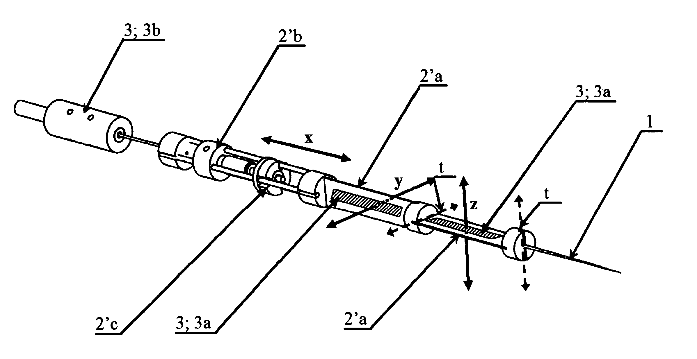
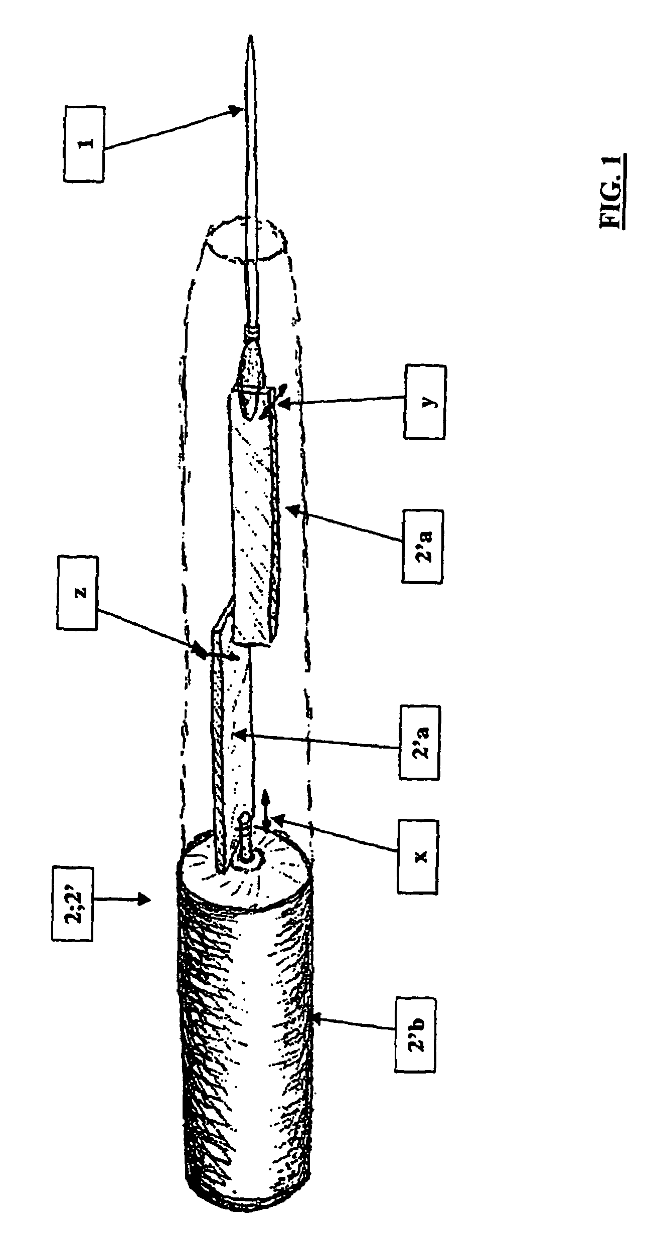
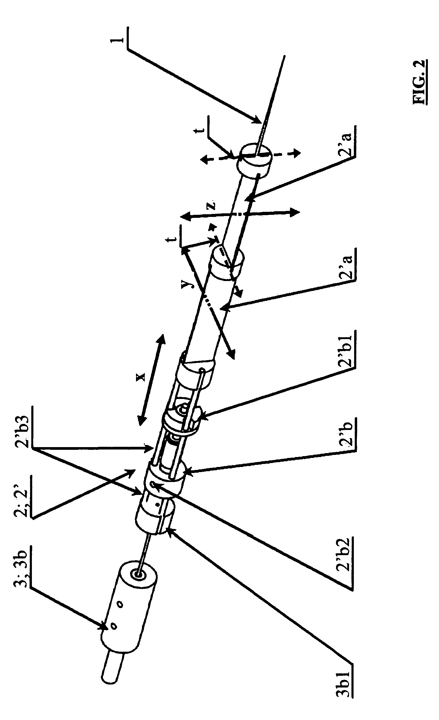
[0022]The invention relates to a micromanipulator, which is intended for the positioning / localization of an operating instrument 1 coupled therewith, by controlling its movement in a single- or multi-axial system of coordinates, such as in the direction of an x-, y- and / or z-axis, by means of electrical actuators 2 present in the micromanipulator. Especially, for providing a substantially elongated structure for the micromanipulator, shown e.g. in FIG. 1 on a level of principle, one or more actuators 2; 2′ enabling the positioning / localization of the operating instrument 1, for providing at least one of its desired directions of motion, are implemented in the way of a piezoelectric bender. In this context, the actuator 2; 2′, producing an axial direction of motion x for the micromanipulator and located on the same longitudinal axis x as a bender 2′a coupled therewith, is implemented in the way of a linear motor 2′b.

[0023]In a particularly preferred application, with reference to th...


PUM


Abstract

A micromanipulator for positioning / localization of an operating instrument coupled therewith. The micromanipulator controls movement of the operating instrument in a single- or multi-axial system of coordinates with one or more electrical actuators. The electrical actuators are especially for providing a substantially elongated structure for the micromanipulator. The one or more actuators including a piezoelectric bender enable the positioning / localization of the operating instrument for providing at least one desired direction of motion.

Description

CROSS-REFERENCE TO RELATED APPLICATIONS[0001]This application claims priority to Finnish patent application 20012410 filed 7 Dec. 2001 and Finnish patent application 20021613 filed 10 Sep. 2002 and is the national phase under 35 U.S.C. §371 of PCT / FI02 / 00964.FIELD OF THE INVENTION[0002]The invention relates to a micromanipulator, which is intended for the positioning / localization of an operating instrument coupled therewith, by controlling its movement in a single- or multi-axial system of coordinates, such as in the direction of an x-, y- and / or z-axis, by means of electrical actuators present in the micromanipulator, whereby, especially for providing a substantially elongated structure for the micromanipulator, one or more actuators enabling the positioning / localization of the operating instrument, for implementing at least one of its desired directions of motion, are provided in the way of a piezoelectric bender. Preferred application environments or targets for a micromanipulato...

Claims


Application Information

Patent Timeline
Patent Type & Authority Patents(United States)
IPC IPC(8): H02N2/00G02B21/32B25J7/00H01L41/09
CPCB25J7/00H01L41/0953H01L41/0966H10N30/2044H10N30/2046
Inventor KALLIO, PASIZHOU, QUANNOVOTNY, MAREKKOIVO, HEIKKIKUNCOVA, JOHANARONKANEN, PEKKATURUNEN, JUHA
Owner CHIP MAN TECH
Why Eureka
Try Eureka