
Non-destructive determination of magnetic permeability tensor in materials of arbitrary shape

a magnetic permeability tensor and non-destructive technology, applied in the direction of permeability measurement, magnetic measurement, instruments, etc., can solve the problems of material destruction, material destructive, and complex known methods

Inactive Publication Date: 2011-06-16
HER MAJESTY THE QUEEN & RIGHT OF CANADA REPRESENTED BY THE MIN OF NATURAL RESOURCES
View PDF19 Cites 5 Cited by
  • Summary
  • Abstract
  • Description
  • Claims
  • Application Information

AI Technical Summary

Problems solved by technology

However, these are destructive to the material, in that these known methods involve the removal of a sample from the material.
For materials which are isotropic, the known methods can be expected to be reasonably accurate, but they are destructive to the material.
Furthermore, for larger samples, in addition to being destructive, the known methods are complex and time consuming.
However, for materials which are magnetically anisotropic, in addition to being destructive, the accuracy of the methods is seriously compromised in that the known methods are only capable of providing an average value of one component of the permeability tensor over a large volume of material, and usually in the axial direction of the ring.
In addition, any stress in the subject material will further invalidate the obtained results, which will be at best approximate if the stress is substantially smaller than the σy=0.2%—yield strength of the material.
Still further, histeresigraphs used for the known methods require an alternating current (AC), and measurements with histeresigraphs are very time-consuming.
However, AC can only be used effectively for diamagnetic and paramagnetic materials, where the relation between the magnetic induction vector B and the field strength vector H is essentially linear, as discussed in more detail below.

Method used


Image

  • Non-destructive determination of magnetic permeability tensor in materials of arbitrary shape
  • Non-destructive determination of magnetic permeability tensor in materials of arbitrary shape
  • Non-destructive determination of magnetic permeability tensor in materials of arbitrary shape

Examples


Embodiment Construction

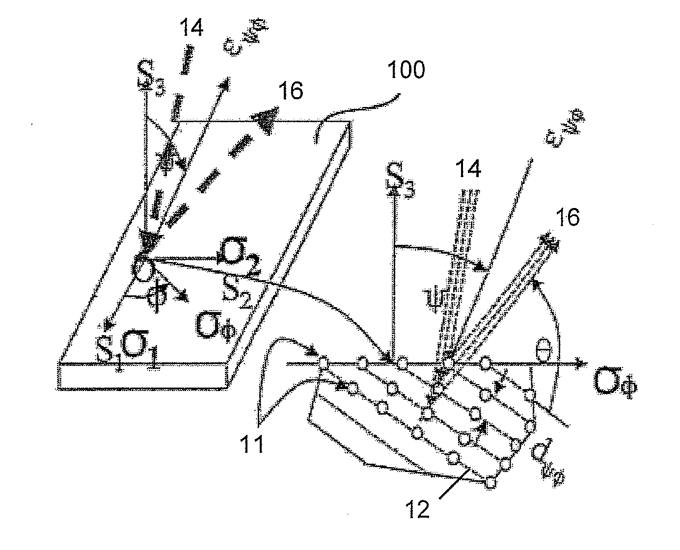
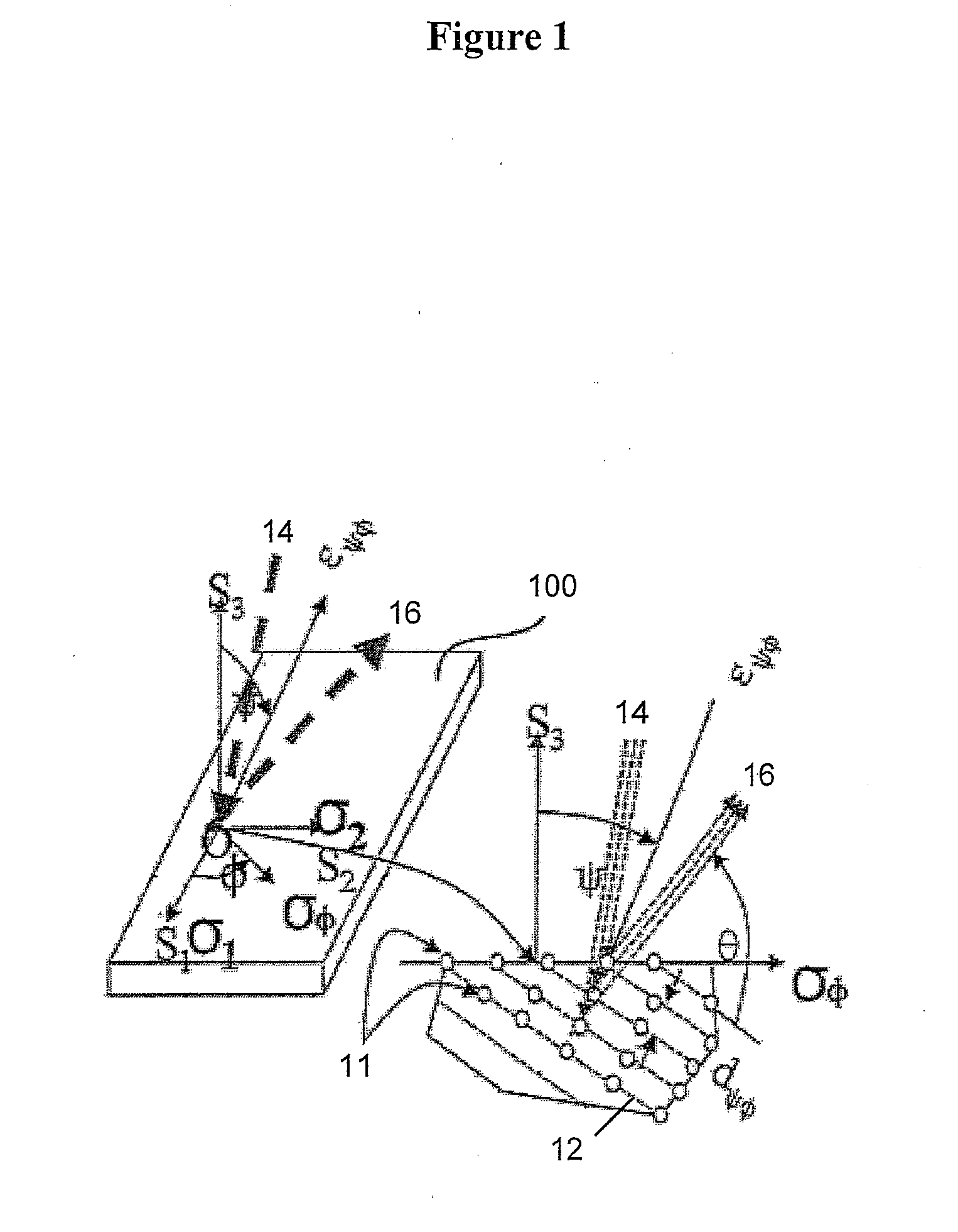
[0027]Referring first to FIG. 1, the first step in the method of the invention is to determine whether there is stress in the subject material, so that compensation for this factor can be made in the determination of the magnetic permeability of the material. The stress is measured at a selected surface of the material, by an X-ray diffraction process, using known equipment. The figure shows the measurement of strain at the selected location at which the incident X-ray beam is shown as 14 and the diffracted X-ray beam as 16. The principal stress components are shown as σl and σ2, in directions S1 and S2, respectively, at the location O of strain measurement εψφ on the surface 100, with atomic planes 12 and their spacing dψφ, such that

dψϕ-d0d0

denotes the strain εψφ measured in the horizontal φ-direction along the σφ-stress direction, and at the ψ-angle from the normal σ11×σ22 to the material surface formed by the principal directions σ11 and σ22; and dψφ denotes the spacing of (imagi...


PUM


Abstract

A method of non-destructive determination of a local magnetic permeability tensor of a material comprises testing by X-ray diffraction on a first surface to identify and measure any surface stress in the material; performing a calibration test using magnetostriction to identify any effect of any determined stress; subjecting the material to a magnetic field having a strength H and measuring a field of induction B on the surface at the selected location and repeating this step by using gradual increases of H until a saturated value is determined for B, to determine a distribution of magnetic domains at the selected location; repeating the determinations of saturated values for B at additional locations on each selected surface of the material; and using the saturated values and distribution of magnetic domains to derive the magnetic permeability tensor. The non-destructive method provides increased accuracy for stressed or unstressed materials of arbitrary shape.

Description

FIELD OF THE INVENTION[0001]This invention relates to methods of determination of magnetic permeability of materials, and in particular to a method of non-destructive determination of a local magnetic permeability tensor in stressed or unstressed materials of arbitrary shape.BACKGROUND OF THE INVENTION[0002]Methods of determination of the magnetic permeability of materials are known. However, these are destructive to the material, in that these known methods involve the removal of a sample from the material. The usual method for this determination is to remove a ring of the material, known as a Rowland ring, around which primary and secondary coils are wound up, and connected to a histeresigraph, which identifies and records the resulting values when a current is passed through the coils to generate a magnetic field around the ring.[0003]For materials which are isotropic, the known methods can be expected to be reasonably accurate, but they are destructive to the material. Furthermo...

Claims


Application Information

Patent Timeline
IPC IPC(8): G01R33/12
CPCG01R33/1223
Inventor ROY, GEORGE
Owner HER MAJESTY THE QUEEN & RIGHT OF CANADA REPRESENTED BY THE MIN OF NATURAL RESOURCES
Learn More