
Sealing System and Method

Inactive Publication Date: 2011-06-16
DEWALCH NORMAN BINZ +2
View PDF11 Cites 1 Cited by
  • Summary
  • Abstract
  • Description
  • Claims
  • Application Information

AI Technical Summary

Benefits of technology

[0017]Another object of the present invention is to provide a locking assembly that can be installed without special tools.
[0070]In another example embodiment of the system the second handle is frictionally pivotable with respect to the actuator housing so as to prevent unwanted pivoting of the second handle to an open position, and wherein a part of the head member is prevented from being inadvertently released after using the means for manipulating the head member to break the fracturable member.
[0077]In another example embodiment of the system the lock housing is in functional cooperation with the at least a part of the shaft portion such that the distal end of the shaft portion is adapted to bear against the lock housing, and wherein the lock housing rather than the fracturable member receives any undesired generally translational force transmitted through the engageable end so as to prevent unintended breaking of the fracturable member.
[0104]In another example embodiment of the method the second handle is frictionally pivotable with respect to the actuator housing so as to prevent unwanted pivoting of the second handle to an open position, and wherein a part of the head member is prevented from being inadvertently released after the step of manipulating the head member to break the fracturable member.
[0111]In another example embodiment of the method the lock housing is in functional cooperation with the at least a part of the shaft portion such that the distal end of the shaft portion is adapted to bear against the lock housing, and wherein the lock housing rather than the fracturable member receives any undesired generally translational force transmitted through the engageable end so as to prevent unintended breaking of the fracturable member.
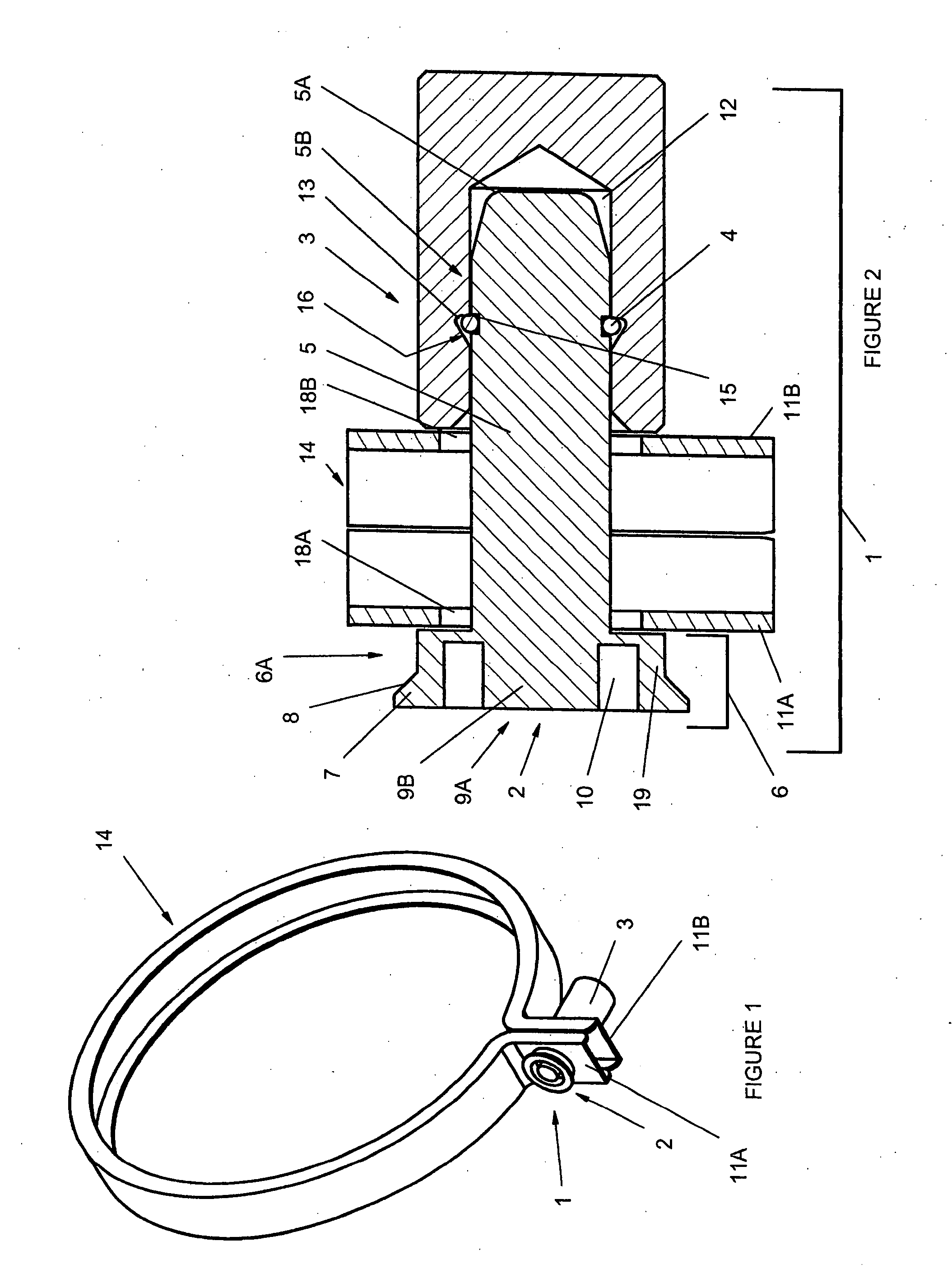
[0141]In another example embodiment of the seal, the retaining recess is formed in part by a first wall of the retainer, the first wall being in spaced in opposing relation to an inclined wall oriented at an angle with respect to the first wall, and wherein the first wall is in functional cooperation with the inclined wall so as to reduce the clearance between the retaining member and the retaining recess when the retaining member is retained within the retaining recess, so as to foster hindering access and removal of the retaining member from retaining recess.

Problems solved by technology

However, with this type of design, high lock cost and operator “key control” may be a potential problem.
Moreover this type of design may require the use of special tools and structures to secure a ring locking device and may require used of more than one hand to retain or engage the locking device.
A frangible portion of the pin is severable in response to relative rotation between its nose and enlarged head to thereby destructively disassemble the locking device.
There is also a need for a locking or securing device that can be “locked” without the need for special tools and “unlocked” only one time by using a special or complementary tool, such that when the locking apparatus is “unlocked,” it is rendered ineffective as a future locking device.

Method used


Image

  • Sealing System and Method
  • Sealing System and Method
  • Sealing System and Method

Examples


Embodiment Construction

[0219]Turning now descriptively to the drawings, in which similar reference characters denote similar elements throughout the several views, the attached figures illustrate an apparatus for securing a plurality of structures or a portion of a utility service enclosure. For example, in one embodiment, the apparatus is used for securing a watthour meter socket ring so as to prevent the separation of two opposing members of the watthour meter socket box ring. The apparatus may be used for creating a tamper-evident seal by securably connecting a plurality of structures. The apparatus may also be used as a locking assembly with at least one structure as will hereinafter be explained in further detail.

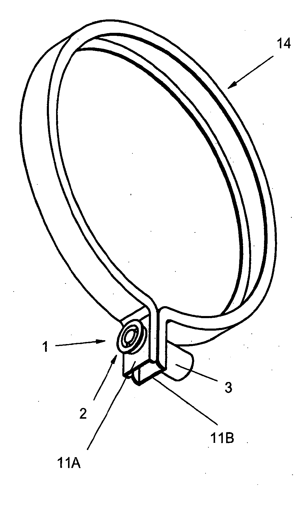
[0220]Referring now to FIG. 1, there is shown a securing sealing ring 14 for a ringed-type meter box (not shown). In order to hold a meter (not shown) in place and prevent its removal from the meter box, both the meter and meter base incorporate a corresponding set of flanges (not shown) tha...


PUM


Abstract

An apparatus for connecting a plurality of structures, such as ends of a sealing ring, with each end defining an aperture therein and with the ring being adapted to mount a meter to a meter box structure. The apparatus comprises a locking pin with a distal end adapted to be insertable through each of the apertures of the first and second ends of the ring. The locking pin comprises a head member having at least an engageable end and a fracturable member. The locking pin further comprises a shaft portion having the distal end. The apparatus further comprises a lock housing adapted to retain at least a part of the shaft portion such that the first and second ends of the ring are connected between the head member of the locking pin and the lock housing. The head member has an outer surface adapted to receive at least two opposing forces, the at least two opposing forces being of sufficient magnitude to break the fracturable member. A lock removal tool is adapted to receive and fracture a portion of the locking pin, enabling removal of the lock assembly from the meter box sealing ring. In an example embodiment an apparatus and method is provided for securing at least one structure or a plurality of structures, used with a utility service enclosure, or for example, a meter box locking ring having, for example, flanged ends or used to seal for example, utility enclosures, meter boxes or trucking, shipping, airline or other transportation containers or enclosures. An example embodiment also provides a tamper-evident locking apparatus or seal that is adapted to indicate tampering.

Description

CROSS-REFERENCE TO RELATED APPLICATIONS[0001]This application is a continuation-in-part of application Ser. No. 11 / 824,156, filed Jun. 26, 2007 which is a continuation-in-part of application Ser. No. 11 / 698,616, filed Jan. 25, 2007, which is a continuation-in-part of application Ser. No. 11 / 444,550, filed May 31, 2006, which claims the benefit of U.S. Provisional Patent Application No. 60 / 685,322, filed May 31, 2005. This application also is a continuation-in-part of International Application No. PCT / US2006 / 021137, filed May 31, 2006. This application also claims the benefit of U.S. Provisional Patent Application No. 60 / 997,326, filed Sep. 30, 2007.[0002]The instant application claims priority to each of the above-referenced applications. All written material, figures, and other disclosure in each of the above-referenced applications to the fullest extent permitted are hereby incorporated by reference.BACKGROUND OF THE INVENTION[0003]The present invention relates generally to a lock...

Claims


Application Information

Patent Timeline
IPC IPC(8): F16B17/00
CPCG01R11/24Y10T403/11G09F3/0329G09F3/0317F16B2200/63
Inventor DEWALCH, NORMAN BINZSTAOHOWLAK, JR., JOHN EDWARDDAVIDSON, ZACHARY LEROY
Owner DEWALCH NORMAN BINZ
Learn More