Device and method for frothing a liquid

a technology of liquid frothing and liquid, applied in the field of liquid frothing devices, to achieve the effect of improving cleanability

Active Publication Date: 2011-06-16
VERSUNI HLDG BV
View PDF10 Cites 14 Cited by
  • Summary
  • Abstract
  • Description
  • Claims
  • Application Information

AI Technical Summary

Benefits of technology

[0009]It is an object of the present invention to provide a device for frothing a liquid such as milk, which may comprise a mechanical pump, which is capable of switching between a process of heating the frothed liquid and a process of leaving the frothed liquid in a cold state, and which has an improved cleanability. This object is achieved by a device comprising pumping means, liquid supplying means and gas supplying means as mentioned in the foregoing, and further comprising means for supplying steam to the pumping means, at the fluid outlet side of the pumping means.
[0010]According to the present invention, steam is fed directly into the pumping means, i.e. the means where a liquid and a gas for frothing the liquid are mixed and where, consequently, a frothing process takes place. This way of doing has a number of important advantages. In the first place, it is not necessary to have an additional heating chamber or the like. In general, as steam is used for heating, the frothing device may come without additional heat conduction surfaces, so that the possibility of heating a frothed liquid is realized without increasing an area to be cleaned. In the second place, the steam may very well be used to steam-clean the inside of the pumping means. In the third place, only using steam for the purpose of heating allows for switching between hot and cold without big rest warmth effects. In the fourth place, the frothing device can be compact and simple on the basis of the fact that all functions of pumping, frothing and heating are combined.
[0011]Within the scope of the present invention, the pumping means may comprise any suitable type of mechanical pump, i.e. any pump which is capable of mixing a liquid and a gas for the purpose of producing froth, and of realizing a displacement of the various fluids from a fluid inlet side to a fluid outlet side. For example, the pumping means may comprise a gear pump having two meshing gears. In that case, it is preferred if the steam supplying means are adapted to supply steam right behind a meshing area of the gears as seen in a direction from the fluid inlet side to the fluid outlet side of the gear pump, as in that way, it is possible to realize an optimal heating process of frothed liquid without affecting the pumping and frothing functions of the gear pump. In particular, it is advantageous if the steam supplying means are adapted to supply steam to the gear pump in a flow that is oriented substantially parallel to axes of rotation of the gears of the gear pump. In that case, the steam is directed such as to mainly flow alongside the gears, and the most of its heating capacity may actually be used for heating the produced froth.
[0014]The present invention further relates to a method for cleaning the pumping means of the frothing device, wherein steam is supplied to the pumping means by the steam supplying means of the device. Steam-cleaning yields good results, and the fact that the steam supplying means are suitable to be used for performing two different functions, namely performing a heating process of the frothed liquid or performing a cleaning process of the pumping means, contributes to a compact design of the frothing device.

Problems solved by technology

A disadvantage of applying a heater which is adapted to transfer heat to milk froth on the basis of conduction, like a continuous-flow heater, is the necessity for cleaning a surface of the heater which serves for contacting the milk froth.
The same disadvantage is encountered when applying a mechanical pump for producing milk froth, as it is necessary to clean the inside of the pump after use.

Method used


Image

  • Device and method for frothing a liquid
  • Device and method for frothing a liquid
  • Device and method for frothing a liquid

Examples


Embodiment Construction

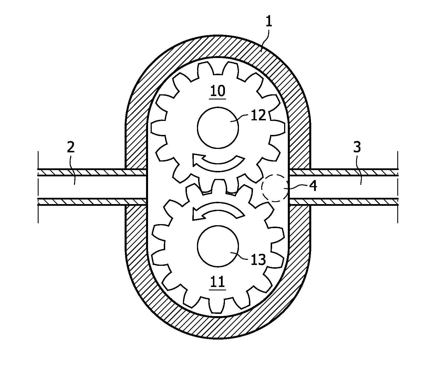
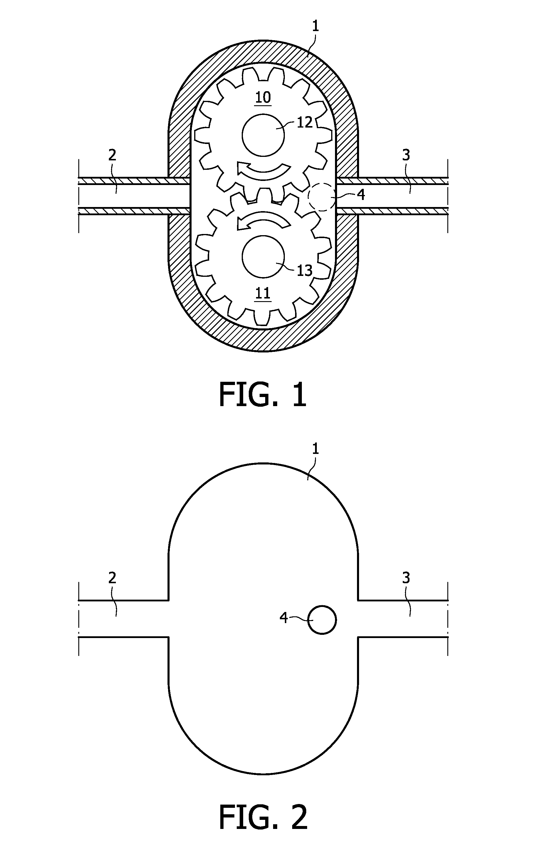
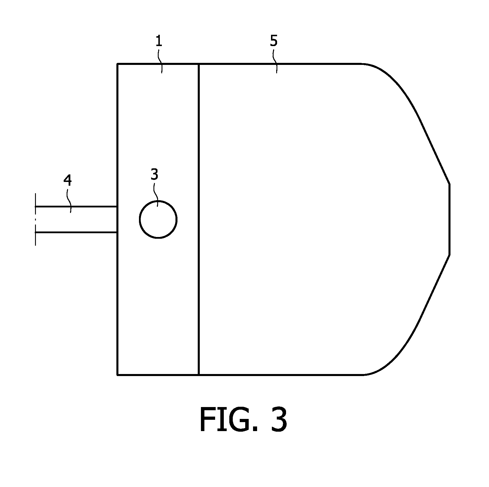
[0020]The figures show a gear pump 1 which is part of a frothing device according the present invention, and portions of various tubes 2, 3, 4 which are connected to the gear pump 1 for supplying a fluid to the gear pump 1 or discharging a fluid from the gear pump 1. The frothing device according to the present invention is not shown as a whole, and it is noted that in general, the frothing device is adapted to produce froth by mixing a liquid and a gas. In the following description, it will be assumed that the liquid is milk and that the gas is air, which does not alter the fact that other fluids may be chosen within the scope of the present invention.

[0021]It will be understood that the frothing device has inlets for letting in the milk and the air, and an outlet for letting out milk froth. The frothing device may further comprise a suitable container for containing a quantity of the milk. The gear pump 1 serves for drawing the milk and the air to its inside, mixing these two ingr...


PUM


Abstract

A device for producing froth comprises means (1) which are adapted to perform a pumping function and to perform a mixing process of at least one liquid and a gas at the same time. Furthermore, the device comprises suitable means (2) for supplying the liquid and the gas to the pumping means (1), and suitable means (3) for discharging froth from the pumping means (1). In order for the device to be capable of producing hot froth, means (4) for supplying steam are provided, and arranged such as to supply the steam directly to the pumping means (1), in particular to an outlet side of the pumping means (1). This way of attributing a heating functionality to the pumping means (1) has many advantages, including the option of a most compact design. Furthermore, the steam may be used for cleaning the pumping means (1).

Description

FIELD OF THE INVENTION[0001]The present invention relates to a device for frothing a liquid such as milk, comprising:[0002]means which are adapted to perform a pumping function, particularly to displace a fluid from a fluid inlet side to a fluid outlet side while increasing a pressure in the fluid;[0003]means for supplying the liquid to the pumping means, at the fluid inlet side of the pumping means; and[0004]means for supplying a gas such as air to the pumping means, at the fluid inlet side of the pumping means.[0005]Furthermore, the present invention relates to a beverage maker such as a coffee appliance or an espresso appliance, comprising a frothing device as mentioned, and to a method for frothing and heating a liquid such as milk, wherein means which are adapted to perform a pumping function, particularly to displace a fluid from a fluid inlet side to a fluid outlet side while increasing a pressure in the fluid, are provided for mixing the liquid and a gas and thereby frothing...

Claims


Application Information

Patent Timeline
Patent Type & Authority Applications(United States)
IPC IPC(8): A47J31/44B08B9/00A23C3/033A23P1/16A23P30/40
CPCA47J43/121A47J31/4485A47J31/44A47J43/12
Inventor DOUMA, SIPKE THEO
Owner VERSUNI HLDG BV
Why Eureka
Try Eureka