

Vehicular drive apparatus
a technology of drive apparatus and lubricating oil, which is applied in the direction of battery/cell propulsion, electric devices, gearing, etc., can solve the problems of complex structure, reduce the size, weight and cost of the drive apparatus, and simplify the structure of the lubricating oil passag
- Summary
- Abstract
- Description
- Claims
- Application Information
AI Technical Summary
Benefits of technology
Problems solved by technology
Method used
Image

Examples
Embodiment Construction
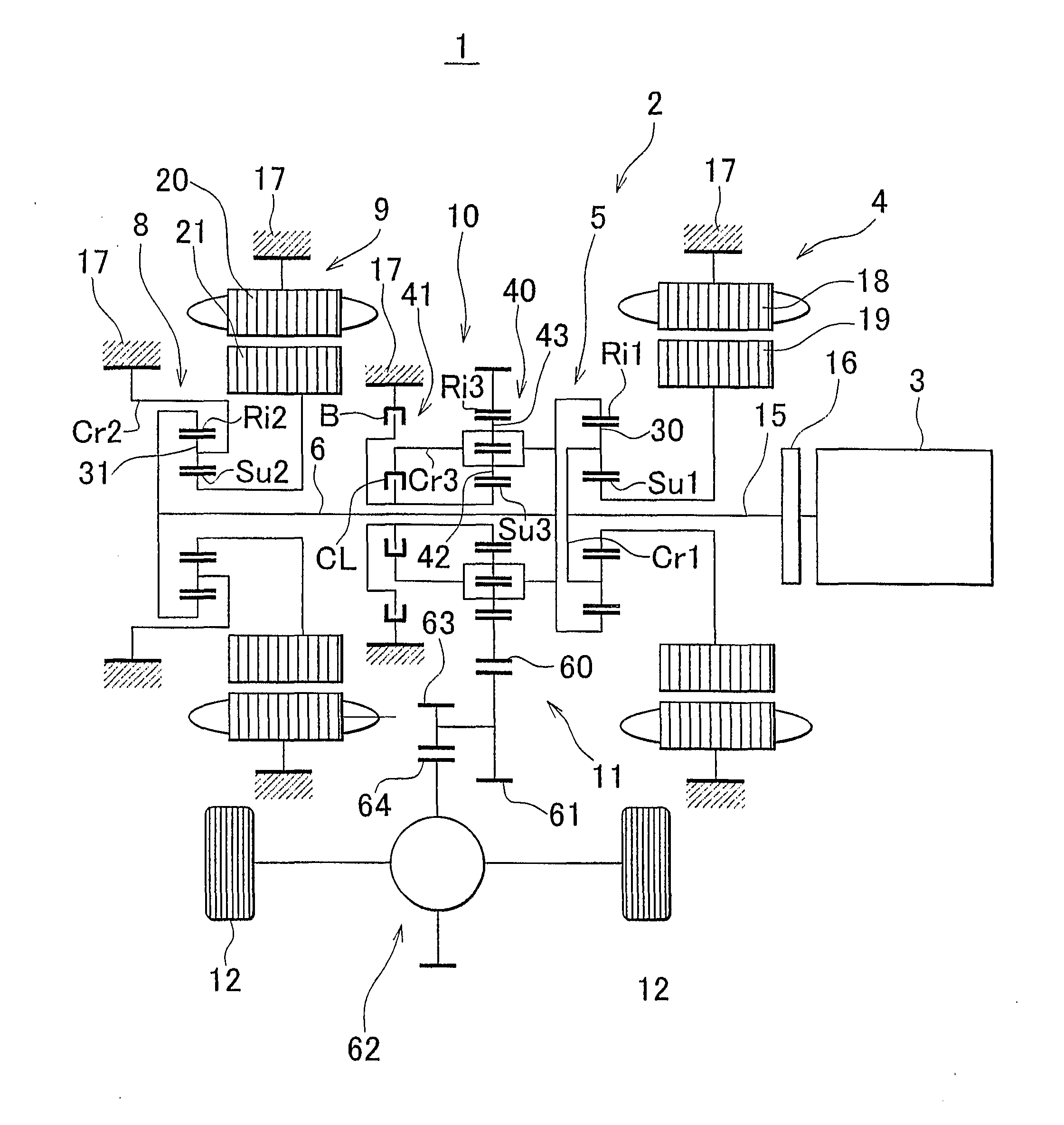
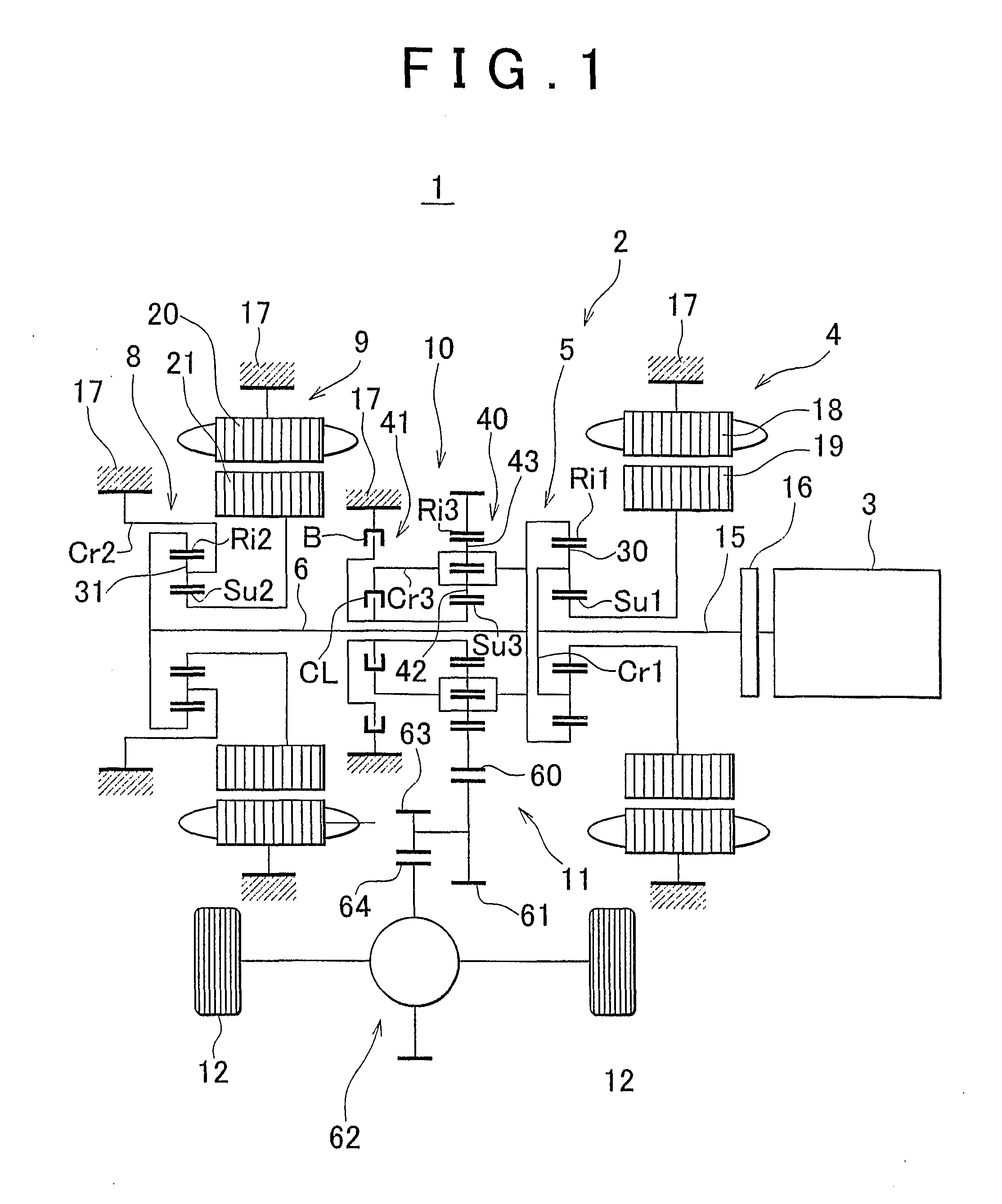
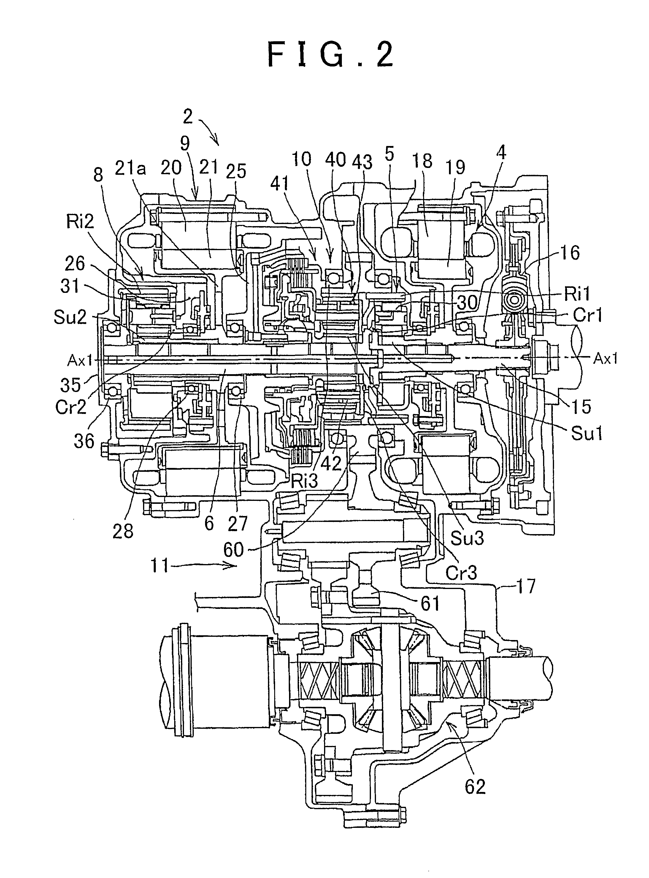
[0025]FIG. 1 is a schematic diagram of the overall structure of a vehicle into which a drive apparatus according to an example embodiment of the invention has been incorporated, and FIG. 2 is a detailed view of the drive apparatus shown in FIG. 1. The vehicle 1 is configured as a so-called hybrid vehicle. As is well known, a hybrid vehicle is a vehicle which is provided with both an internal combustion engine and an electric motor as driving power sources for running. The vehicle 1 has a FF layout in which the driving wheels and the internal combustion engine are positioned in the front of the vehicle.
[0026]A drive apparatus 2 includes a first motor-generator 4, a power split device 5 which serves as a first differential mechanism that is connected to both an internal combustion engine 3 and the first motor-generator 4, and an intermediate shaft 6 which serves as an intermediate rotating member to which power is transmitted from the power split device 5. The drive apparatus 2 is als...
PUM
 Abstract
Description
Claims
Application Information