Optical device and method for shape and gradient detection and/or measurement and associated device

an optical device and gradient detection technology, applied in the direction of optical radiation measurement, instruments, applications, etc., can solve the problems of increasing the size of the device, increasing the cost needed to achieve stable operation, and losing the shape information in the thickness direction of the sample,

Inactive Publication Date: 2011-06-16
TOHOKU UNIV
View PDF23 Cites 39 Cited by
  • Summary
  • Abstract
  • Description
  • Claims
  • Application Information

AI Technical Summary

Benefits of technology

[0071]In accordance with the present invention, a two-dimensional polarized light image of an object recorded by a microscope, a telescope, a projection device, or another image formation device can be analyzed, and the gradient angle (0° to 90°) of the surface constituting the object can be detected and/or measured with a precision of 0.01° to 0.001°. It is possible to obtain a device for detecting and/or measuring three-dimensional shapes and gradients, in which the three-dimensional shape of an object can be reconstructed using the measured gradient angles by making use of the fact that the object surfaces are smoothly connected together. Also, the device for this purpose does not require a complex mechanism, and is a simple device for detecting and/or measuring three-dimensional shapes and gradients.
[0072]In the present invention, the gradient angle of a reflection surface is observed using the reflection of polarized light. Change in the polarization state due to reflection is a phenomenon occurs only once in a measurement section. Excluding this reflection phenomenon, change does not occur in the polarization state during the propagation of light. Since the incident polarized light and the output polarized light after reflection both pass through air, liquid, or another isotropic uniform medium, change does not occur in the polarization state during propagation of light. Therefore, the most important feature is the point that [polarized light] is not affected by the observation environment and the observation distance.
[0073]In the present invention, the gradient of an object can be read directly. Various applications are possible by simple image processing because local variations in the gradient can also be precisely observed without contact. In particular, since the environment is irrelevant, a novel device for detection and measurement can be ...

Problems solved by technology

In such a case, the projected surface is a CCD detector or another two-dimensional surface, and information related to shape in the thickness direction of the sample is usually lost.
However, this not only increases the size of the device, but also leads to significantly increased costs needed to achieve stable operation because of the more complex imaging conditions and environment.
However, these methods commonly involve dividing an optical path to form observation light and reference light, and controlling the difference in the optical paths to generate interference fringes and measure the length of the optical path.
Therefore, a special environment must be prepared as a countermeasure to vibrations, temperature fluctuations, and the like because the measurement values are affected by disturbances in the optical paths; and such measures cannot be applied in an ordinary environment.
Therefore, the surface shape, and more particularly the surface gradient, cannot be directly measured.
Sensitivity is high in hologram-based interferometric methods, but the procedures are laborio...

Method used


Image

  • Optical device and method for shape and gradient detection and/or measurement and associated device
  • Optical device and method for shape and gradient detection and/or measurement and associated device
  • Optical device and method for shape and gradient detection and/or measurement and associated device

Examples


example 1

Reduction Optical System Device

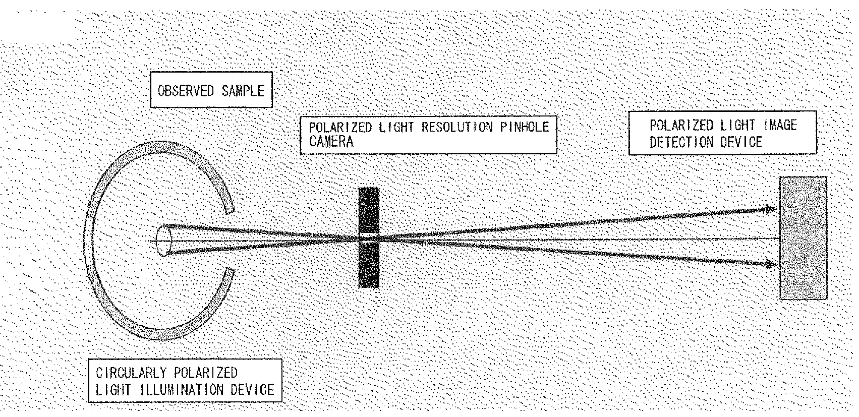
[0251]An example of the first embodiment of the present invention include a shape-measuring telescope, which is a reduction optical system device. FIG. 9 shows the configuration of a shape-measuring telescope in the most simple configuration. The present configuration can be applied to a reduction optical system device and may also naturally be applied to camera or the like.

[0252]The illumination device in the shape and gradient measurement optical device of the present invention is shown as a circularly polarized light illumination device in FIG. 9. The circularly polarized light illumination device can be implemented by surrounding the periphery of the sample with a circularly polarized light panel. Technical elements of the circularly polarized light panel may be composed of elements similar to a liquid crystal panel, and may include a light-emitting diode or another light source, a diffusion plate, a linear polarization film, and a retarder film, a...

example 2

Magnifying Optical System Device

[0258]An example of the second embodiment of the present invention is a shape-measuring microscope, which is a magnifying optical system device. FIG. 10 shows the configuration of a shape-measuring microscope in the simplest configuration. The present configuration can be applied to a magnifying optical system device, and may also be used in various devices without particular limitation as long as the object can be achieved.

[0259]In a magnifying optical system for microscopic measurements and the like, the aperture angle in an imaging system for light flux diverging from a single point on a sample increases as the numerical aperture (NA) of the optical system is increased. Changes in the polarization state in the light flux are thus significantly large enough that the configuration is generally fashioned as shown in FIG. 10.

[0260]When forming an image in the polarized light detection device in a magnifying optical system, the NA of the optical system ...

example 3

Other Shape-Measuring Optical Devices

[0265]The optical device for shape and gradient measurement of the present invention may be, for example, a device such as shown in the schematic diagrams of FIG. 12 or 13. It should be understood that the depicted devices can be configured using a combination of known techniques, and that many alterations and modifications can be made. The optical system and the collimator optical system may be configured using lenses, or the optical system may be configured using mirrors in an optical system that uses white light or multi-wavelength light. In the case of a configuration such as shown in FIG. 12, variation in the phase and amplitude at the mirror surface may be measured and corrected in advance as required. A folding reflector may have an aperture in the center. In a typical configuration, the optical system between the polarized light illumination device and the polarized light image detection device may include a reflection imaging system, a b...


PUM


Abstract

Provided are: an optical device for shape and gradient detection and/or measurement which has a simple structure, is robust to external disturbance, and enables accurate measurement of the gradient angle of an object surface, including a human body; a method for optical shape and gradient detection and/or measurement; and a circularly polarized light illumination device. The optical device for shape and gradient detection and/or measurement uses the optical reflection characteristics of the surface of an object to detect and/or measure the surface shape or gradient of an observed object, and is provided with an illumination device and a polarized light image detection device. The illumination device makes the incident light, which surrounds the periphery of the object and is essentially a known perfect polarized light, fall uniformly. The polarized light image detection device detects a polarized light ellipse of the perfectly polarized light component of a light beam group, which is specularly reflected by the object surface and radiated at a particular azimuth angle. The optical device measures the gradient angle with respect to the radiated light beam of the reflection surface in a step 1 in which the orientation of the incident plane is detected from the observed azimuth angle value of the polarized light ellipse for the reflecting surface of the object which forms an incident point for each reflected and radiated light beam, and a step 2 in which the incident angle is detected from the ellipticity logic value of the polarized light ellipse. The method for optical shape and gradient detection and/or measurement is carried out using the same operation.

Description

TECHNICAL FIELD[0001]The present invention relates to an optical device for shape and gradient detection and / or measurement, and to a method for extracting object information. The present invention particularly relates to an optical device for shape and gradient detection and / or measurement of an observation sample and to a method for extracting object information, the device and method being advantageous in shape-measuring microscopes, biological microscopes, shape-measuring telescopes, medical diagnostic devices, mammography devices, gradient sensors, and the like. The present invention also relates to a circular polarized light illumination device and method, and particularly relates to a circular polarized light illumination device for observation samples advantageous in shape-measuring cameras, biological microscopes, shape-measuring telescopes, devices for measuring the inner surface shape of cylinders or the like, devices for measuring aspheric shapes, mammography devices, gr...

Claims


Application Information

Patent Timeline
IPC IPC(8): A61B6/00G01B11/24
CPCA61B5/0064A61B5/0091A61B5/1077G02B27/28G01B11/24G02B21/0092A61B5/4312
Inventor YAMAMOTO, MASAKITSURU, TOSHIHIDE
Owner TOHOKU UNIV
Why Eureka
Try Eureka