Mass spectroscope and method of calibrating the same

a mass spectroscope and mass spectrometer technology, applied in the direction of calibration apparatus, separation processes, instruments, etc., can solve the problems of reducing the efficiency of ionization, difficult to keep ions stably in the ion trap, etc., and achieve the effect of high efficiency and highly reliable calibration

Active Publication Date: 2005-06-30
HITACHI HIGH-TECH CORP
View PDF3 Cites 18 Cited by
  • Summary
  • Abstract
  • Description
  • Claims
  • Application Information

AI Technical Summary

Benefits of technology

[0018] According to the present invention, each time ions are introduced into the ion trap, data corresponding to the total amount of ions introduced to the ion trap is measured and is then used as a reference for correction purposes. It is thus possible to find such a set condition under which ions can be discharged from the ion trap with highest efficiency by taking into consideration the ion intensity changes (fluctuation) due to such factors as problems in the pump, the ion source, etc. In other words, the condition under which ions are actually resonant is observed more accurately to realize highly reliable calibration.

Problems solved by technology

Actually, however, it is very difficult to keep supplying ions stably into the ion trap due to such troubles as deterioration of the performance of the pump that introduces the sample into the ion source, choked pipe, unstable operation of the ion source itself, and decrease in the efficiency of ionization caused by the contamination of the ion source, for example.

Method used


Image

  • Mass spectroscope and method of calibrating the same
  • Mass spectroscope and method of calibrating the same
  • Mass spectroscope and method of calibrating the same

Examples


embodiment 1

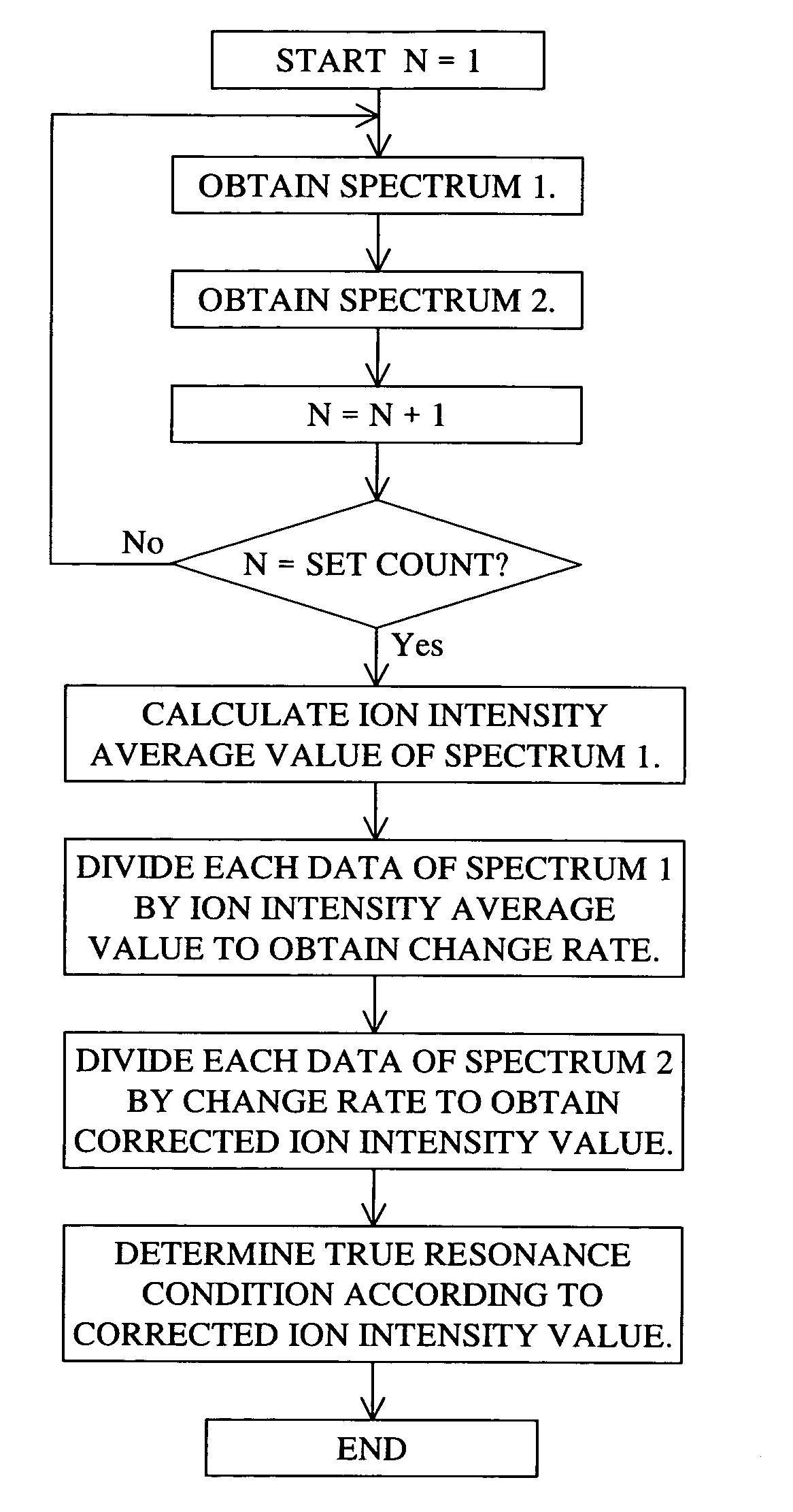
[0043] Next, a description will be made of the flow of a calibration process in the first embodiment with reference to the accompanying drawings.

[0044]FIG. 3 shows a flowchart of the first embodiment.

[0045] At first, “1” is set in the algebraical symbol N in the data processing unit 20 (or control unit 18) to start the processing. At the same time, a standard sample of which the observed mass is known in advance is caused to flow into the ion source 12 at a fixed flow rate, using the sample introducing device 10, so that the sample is ionized. This ionization of the standard sample with the known observed mass is continuously performed until the end of the calibration process.

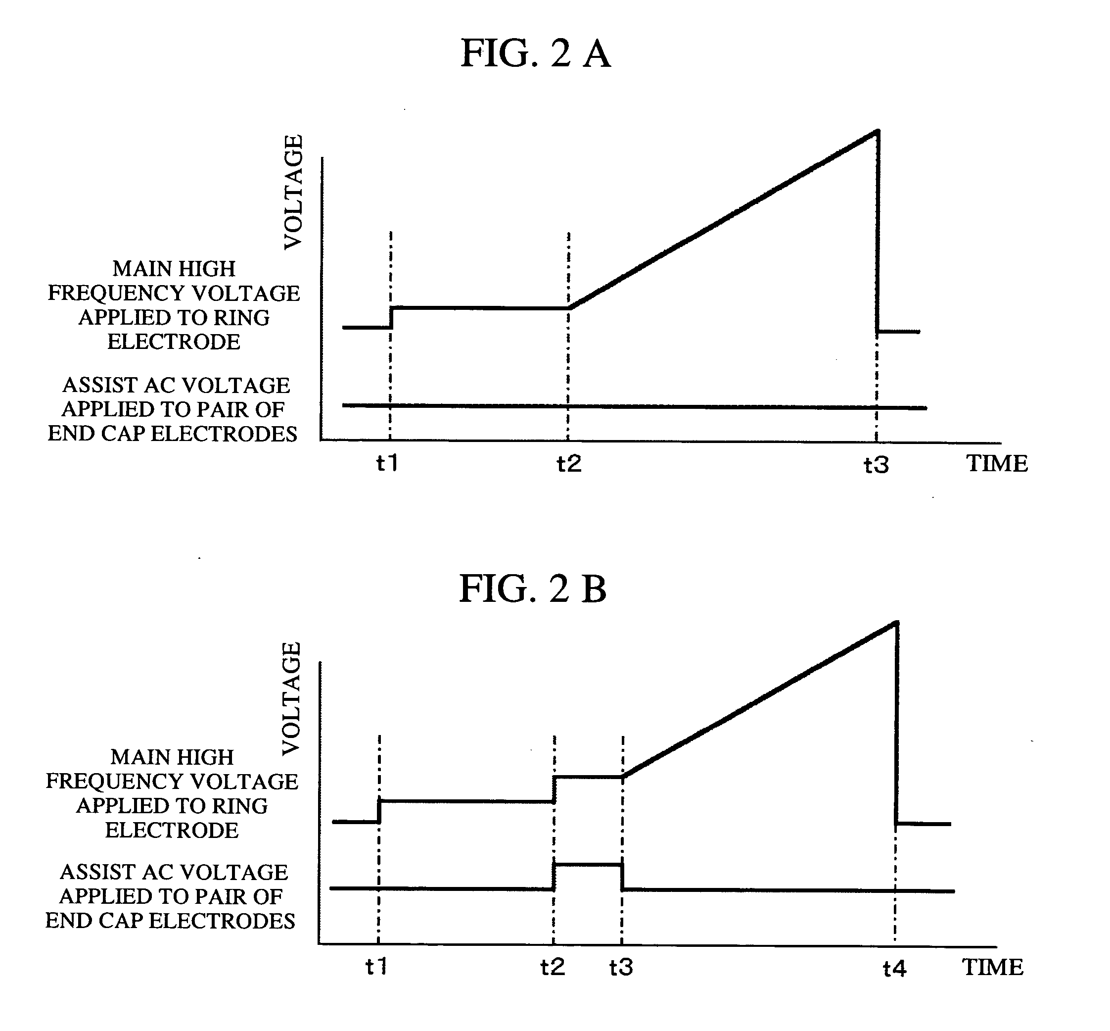
[0046] Thereafter, a spectrum 1 is obtained. FIG. 2A shows an example of the ion trap operation to obtain the spectrum 1. As shown in FIG. 2A, an auxiliary AC voltage is not applied to the end-cap electrodes in this step. Namely, the ion trap is operated using only the main high-frequency voltage to be appli...

embodiment 2

[0056] The calibration in the first embodiment enables both the voltage applied to the ion trap and its frequency to be changed to the optimum condition. And, as a result of the calibration, graphs as shown in FIGS. 4 through 6 are displayed on the display screen of the data processing unit 20. Such a calibration result is usually stored so that the calibration reliability can be confirmed later. Alternatively, however, the information used in the calibration processing as shown in FIGS. 4 and 5 may not be stored while storing only the calibration result as shown in FIG. 6, in order to prevent an increase in the data volume.

[0057] In the first embodiment, the calibration result is obtained as shown in FIG. 6. The Y axis values of that data denote the ion intensity ratio (%) and no absolute value is recorded for the ion intensity. It is sometimes desired to know the measured ion intensity value when later referring to the calibration result. In such a case, the result shown in FIG. ...

embodiment 3

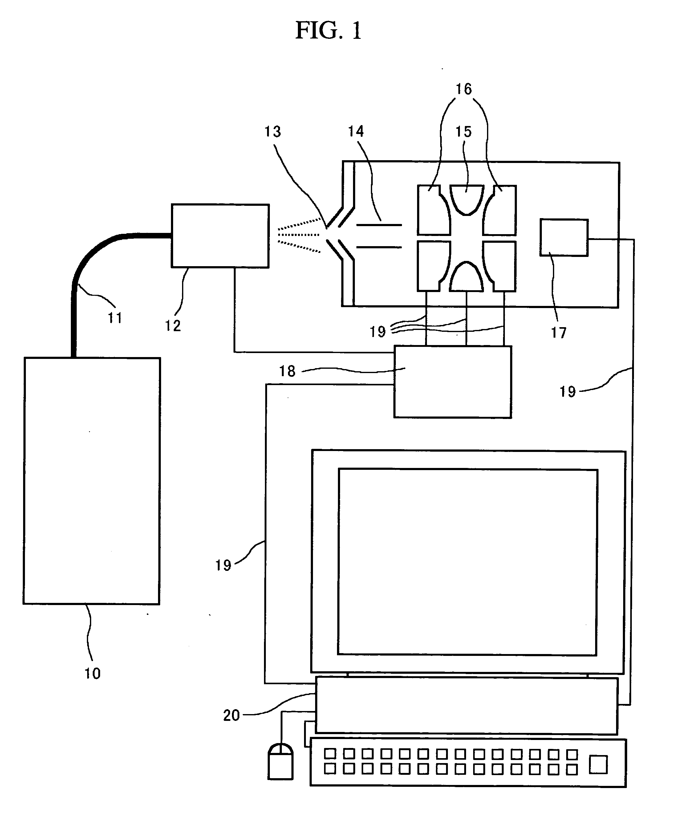
[0062]FIG. 12 shows a block diagram of a third embodiment. The third embodiment differs from the first embodiment in that a time-of-flight type mass spectroscope is disposed in a stage just after the ion trapping device. The time-of-flight type mass spectroscope is used to obtain a mass spectrum by accurately measuring the difference in time between ions when they reach a detector in accordance with their masses after they have been accelerated at the same time.

[0063] In the configuration of the mass spectroscope in this third embodiment, ions discharged from the ion trap travel through the ion transport unit 21, then they are deflected and converged through a deflector 22 and a convergence lens 23. The ions are then accelerated in the orthogonal direction by an ion acceleration unit consisting of a pushing-out electrode 24 and an extraction electrode 25. The accelerated ions are reflected by a reflectron 26, and then reach the detector 27 where they are detected.

[0064] Mass spect...


PUM

PropertyMeasurementUnit
mass numberaaaaaaaaaa
mass spectrumaaaaaaaaaa
massaaaaaaaaaa

Abstract

An ion resonance condition is corrected accurately in an ion trapping device. Measurements are repeated by alternately applying and not applying a resonance frequency voltage while spectral data is obtained continuously. Data obtained in the absence of the resonance frequency voltage is used as reference data to correct the set data of a resonance condition. As a result, calibration can be made while taking into consideration the variations in the amount of ions that are introduced into the ion trap.

Description

BACKGROUND OF THE INVENTION [0001] 1. Field of the Invention [0002] The present invention relates to the calibration of a mass spectroscope that uses an ion trap. [0003] 2. Description of Related Art [0004] An ion trap mass spectroscope comprises a ring electrode having a hyperboloid of revolution of one sheet on the inner surface, and a pair of end-cap electrodes disposed opposite each other across the ring electrode and having a hyperboloid of revolution of two sheets on the inner surface. The space surrounded by the ring electrode and the end-cap electrodes forms an ion trapping area. When a predetermined high-frequency voltage is applied to the ring electrode and the pair of end-cap electrodes, a three-dimensional quadrupole electric field is formed in the ion trapping area, in which ions that are either internally generated or introduced from the outside can be trapped. The thus trapped ions move around in the space inside the electrodes at a frequency specific to their mass. I...

Claims


Application Information

Patent Timeline
Patent Type & Authority Applications(United States)
IPC IPC(8): G01N27/62B01D59/44H01J49/40H01J49/42
CPCH01J49/0009H01J49/424H01J49/0027
Inventor NAGAI, SHINJIYASUDA, HIROYUKINISHIDA, TETSUYA
Owner HITACHI HIGH-TECH CORP
Why Eureka
Try Eureka