
Trouble analysis apparatus

a technology of trouble analysis and trouble, applied in the field of trouble analysis apparatus of computer system, can solve the problems of troublesome operation, limited examination and definition of operations by operators, and the only application of methods, etc., and achieve the effect of troublesome operation, troublesome relationship between trouble events and specific trouble spots

Active Publication Date: 2011-06-16
NEC CORP
View PDF8 Cites 6 Cited by
  • Summary
  • Abstract
  • Description
  • Claims
  • Application Information

AI Technical Summary

Benefits of technology

[0042]In the above-described solutions, the trouble spot is not determined based on a relationship between the trouble events and the specific trouble spots. In the above-described solutions, the trouble spot is determined based on the system topology information (a concept of propagation directions of error operations). Therefore, it is possible to handle very wide range of troubles. In addition, small amount of load and labor are required to the operator because it is not necessary to conduct closely examining operations and defining operations on relationship between the trouble events and the specific trouble spots.

Problems solved by technology

First, regarding a method in which an operator recognizes a trouble notification and determines a trouble spot based on his experiences, there is a limitation because the method is based on the knowledge of a person.
For example, there is a problem in which the method can only applied to troubles similar to the troubles which occurred in the past.
In addition, if the multilayer system which is monitored is extended and / or is complicated, there are presumably difficulties when detecting a trouble spot.
However, such examining and defining operations by the operator are limited due to, for example, knowledge.
Further, closely examining operations and defining operations (registration operations) of relationship between the trouble events and the specific trouble spots are troublesome.
When a system configuration is updated, there is a possibility in which close examining operations and defining operations are necessary again and are troublesome.

Method used


Image

  • Trouble analysis apparatus
  • Trouble analysis apparatus
  • Trouble analysis apparatus

Examples


Embodiment Construction

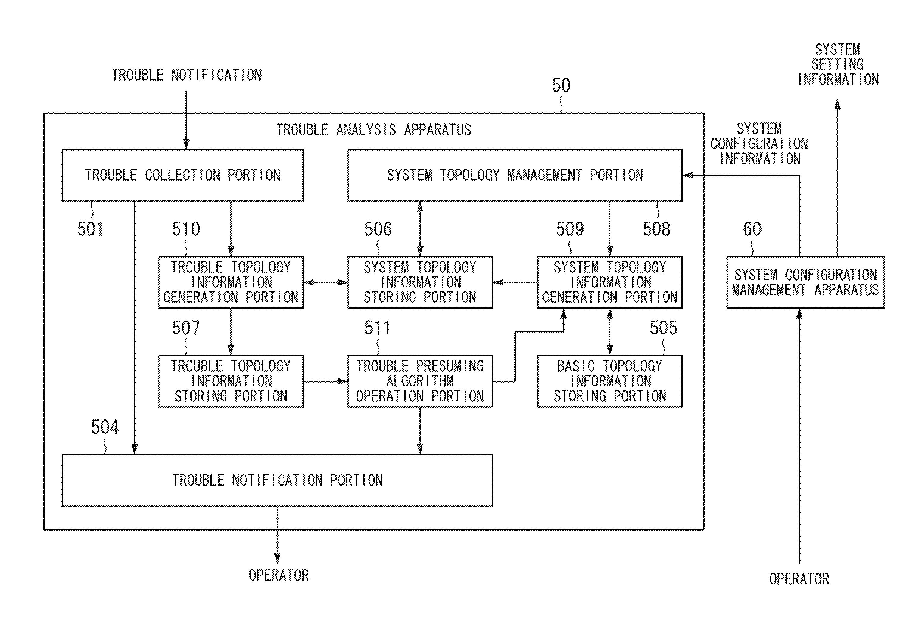
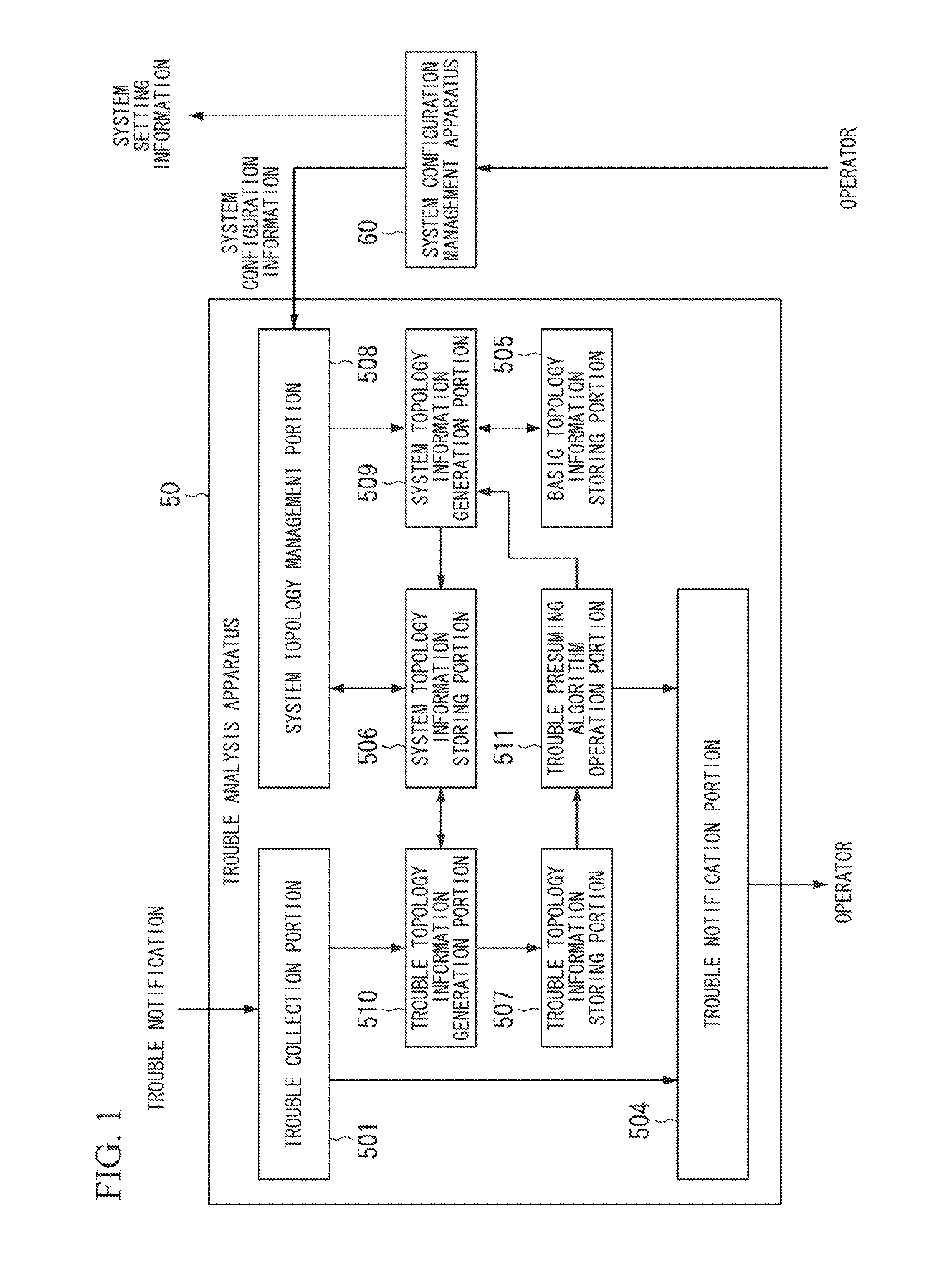
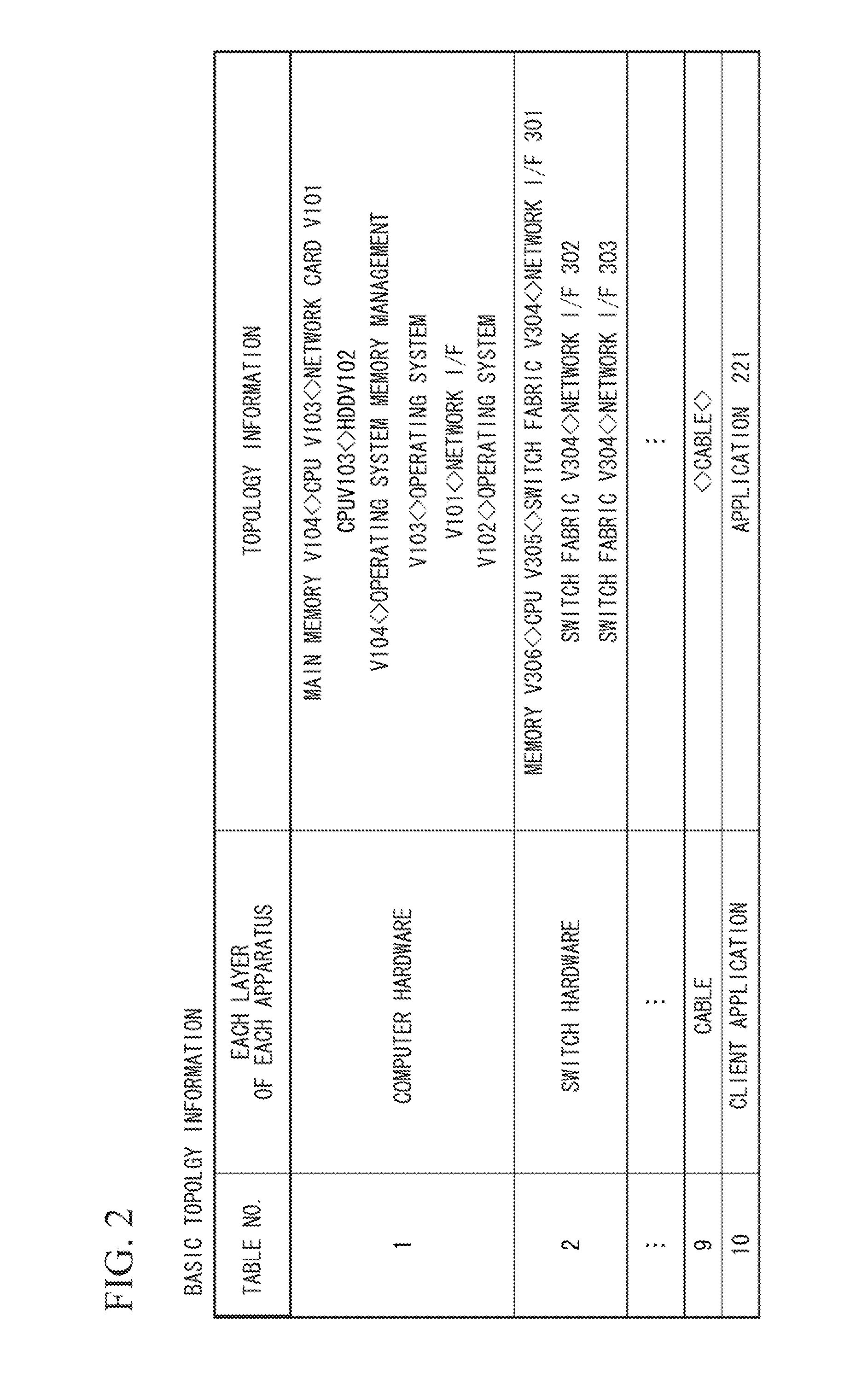
[0063]FIG. 1 is a block diagram of a trouble analysis apparatus 50 in one embodiment. FIG. 2 shows one example of information stored in a basic topology information storing portion 505. The trouble analysis apparatus 50, mainly in reference to system model (system topology information) constituted from both functional elements of all layers from hardware to software belonging to apparatuses that constitute the system and a link between functional elements, determines a functional element (trouble source functional element) which is presumed to be a trouble cause.

[0064]Concretely, as shown in FIG. 1, the trouble analysis apparatus 50 includes a trouble collection portion 501 (corresponding to an error detection information receiving portion of the present invention), a trouble notification portion 504, a basic topology information storing portion 505, a system topology information storing portion 506, a trouble topology information storing portion 507, a system topology management po...


PUM


Abstract

A trouble analysis apparatus is provided which includes: a system topology storing portion; an error detection information receiving portion which collects error detection information; and a trouble source determination portion which, based on both the error detection information collected by the error detection information receiving portion and system topology information stored in the system topology information storing portion, determines a trouble source functional element that is presumed as a functional element which is a source of a system trouble. Links included in the system topology information have information indicating spreading directions of error operations between the functional elements when trouble occurs. When the trouble source detection portion receives the error detection information with regard to multiple error functional elements, the trouble source determination portion sequentially selects one of the multiple error functional elements. The trouble source detection portion determines whether or not directions from the selected error functional element to other error functional elements conform to the spreading directions included in the system topology information. The trouble source determination portion determines the selected error functional element as the trouble source functional element when the spreading directions are conformable.

Description

BACKGROUND OF THE INVENTION[0001]1. Technical Field[0002]The present invention relates to a trouble analysis apparatus of a computer system. Particularly, the present invention relates to a trouble analysis apparatus for determining a cause of a trouble when the computer system has trouble.[0003]Priority is claimed on Japanese Patent Application No. 2008-201272, filed Aug. 4, 2010, the content of which is incorporated herein by reference.[0004]2. Background Art[0005]Today, many computer systems are constituted from hardware and software. In addition, such hardware and software are respectively constituted from elements (hereinafter, “functional elements”) that respectively implement functions. In other words, each apparatus including software constitutes multiple layers from hardware to software. The functional elements belonging to each layer cooperate each other and implement functions as one apparatus (an apparatus with multiple layers including software is called a “multilayer a...

Claims


Application Information

Patent Timeline
Patent Type & Authority Applications(United States)
IPC IPC(8): G06F11/07
CPCG06F11/0706G06F11/079
Inventor HIDAKA, YOUICHIYOSHIKAWA, TAKASHIHIGUCHI, JUNICHI
Owner NEC CORP
Learn More