
Protective glove and method of manufacturing the same

a technology of protective gloves and gloves, which is applied in the field of gloves, can solve the problems of liquids and gases that cannot penetrate the seams of gloves, severe burns, and injury to the wearer, and achieve the effects of improving the cut and penetration strength of gloves, adding comfort and protection

Inactive Publication Date: 2011-06-23
SUMMIT GLOVE
View PDF12 Cites 26 Cited by
  • Summary
  • Abstract
  • Description
  • Claims
  • Application Information

AI Technical Summary

Benefits of technology

The device of the present invention comprises a temperature resistant and fluid impermeable protective glove having front and back panels joined together by at least one seam. During manufacture, the glove is dipped into a first thin liquid to coat the exterior surface of the glove. The first liquid penetrates through gaps in the seam and seals those gaps as it solidifies. The first liquid coated glove is then dipped into a second thicker liquid to coat the entire exterior surface including the sealed seam. A third coating may be applied to the interior surface of the glove prior to joining the front and back panels together. Preferably, the third coating is a blade-coating that improves the gloves cut and penetration strength. The glove may also include an interior liner and an exterior protective member for added comfort and protection.

Problems solved by technology

In many industries, workers may have to handle articles that potentially can injure them.
In the food services industry, for example, workers are frequently exposed to heated surfaces and hot liquids and gases that may cause severe burns.
While gloves currently known in these industries function quite well, one of the problem areas that persists is the tendency for liquids and gases to be able to penetrate the seams of the gloves.
Liquids and gases tend to penetrate into the interior of the glove through these small gaps and thereby cause injury to the wearer.

Method used


Image

  • Protective glove and method of manufacturing the same
  • Protective glove and method of manufacturing the same
  • Protective glove and method of manufacturing the same

Examples


Embodiment Construction

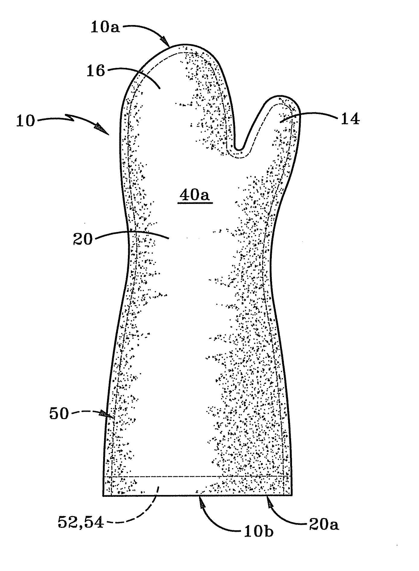
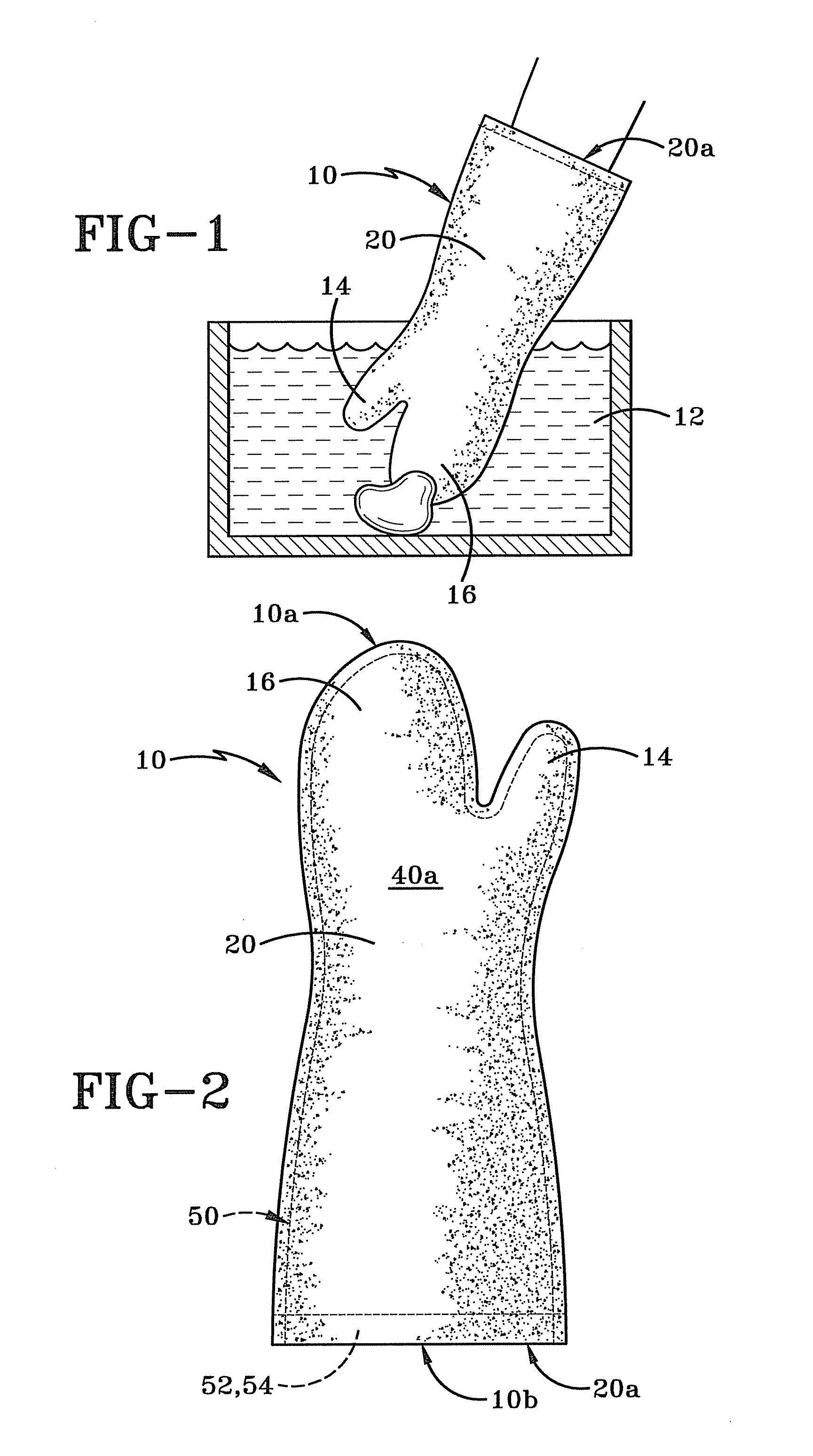
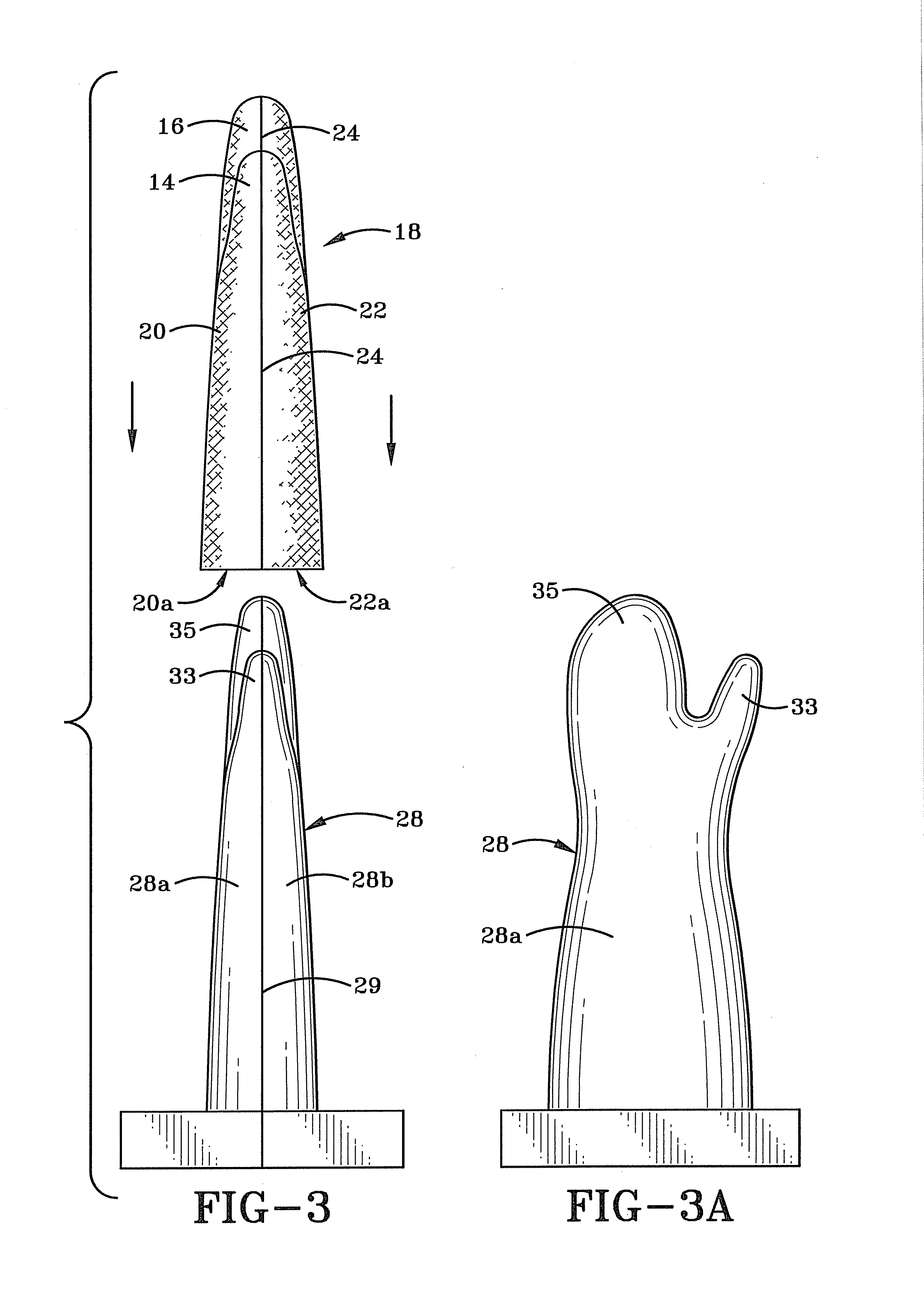
Referring to FIGS. 1-12, there is shown a protective glove in accordance with the present invention and generally indicated at 10. FIGS. 1, 2 and 12 show various details of the structure of glove 10. FIGS. 3-11a illustrate how glove 10 is manufactured and how the process constructs the structure of glove 10. FIG. 11a illustrates an alternative structure for the glove in accordance with the present invention.

Glove 10 as illustrated herein is of a mitt style and includes a thumb region 14 and a single finger region 16 that would cover and protect all four of the wearer's fingers together. It will be understood that if it is desirable to protect the wearer's fingers in a different manner, that glove could alternatively include a thumb region and two, three or four finger regions. These alternative versions of the glove are not illustrated herein but are considered to fall within the spirit and scope of the present invention.

As indicated previously, glove 10 is designed for applications...


PUM

PropertyMeasurementUnit
distanceaaaaaaaaaa
temperature resistantaaaaaaaaaa
lengthaaaaaaaaaa

Abstract

A temperature resistant and fluid impermeable protective glove having front and back panels joined by at least one seam. During manufacture, the glove is dipped into a first thin liquid to coat the exterior surface of the glove. The first liquid penetrates through gaps in the seam and seals those gaps as it solidifies. The first liquid coated glove is then dipped into a second thicker liquid to coat the entire exterior surface including the sealed seam. A third coating may be applied to the interior surface of the glove prior to joining the front and back panels together. The glove may also include an interior liner and an exterior protective member for added comfort and protection.

Description

BACKGROUND OF THE INVENTION1. Technical FieldThis invention generally relates to gloves. More particularly, the invention relates to protective gloves used in industries where workers encounter extremely high or extremely low temperature substances or potentially come into contact with any number of a variety of caustic substances. Specifically, the invention relates to a glove having a first coating on its exterior surface that penetrates and seals the seams and a second coating that overlays the first coating, and to a method of manufacturing gloves incorporating these elements.2. Background InformationIn many industries, workers may have to handle articles that potentially can injure them. In the food services industry, for example, workers are frequently exposed to heated surfaces and hot liquids and gases that may cause severe burns. It has therefore become commonplace for workers in such environments to wear protective clothing, including temperature and fluid resistant gloves...

Claims


Application Information

Patent Timeline
Patent Type & Authority Applications(United States)
IPC IPC(8): A41D19/015D05B23/00A41D19/04A41D19/02
CPCA41D19/015A41D19/0065
Inventor HULL, JAMES L.
Owner SUMMIT GLOVE
Learn More