Vehicular refrigeration cycle apparatus

a technology of refrigeration cycle and electric compressor, which is applied in the direction of domestic cooling apparatus, lighting and heating apparatus, refrigeration components, etc., can solve the problems of sometimes being heard by users, operating noise of electric compressor, and sometimes bothering users, so as to effectively keep the unfamiliar operating nois

Inactive Publication Date: 2011-06-23
DENSO CORP
View PDF0 Cites 29 Cited by
  • Summary
  • Abstract
  • Description
  • Claims
  • Application Information

AI Technical Summary

Benefits of technology

[0016]In the vehicular refrigeration cycle apparatus of the present invention, the masking noise control means (40a) may make the masking noise generating means (12a, 21, 51) generate masking noise when the vehicle is stopped or the vehicle is being driven at a predetermined reference vehicle speed (KVv) or less.
[0017]According to this, it is possible to make the masking noise generating means (12a, 21, 51

Problems solved by technology

As a result, the operating noise of the electric compressor will sometimes bother the user.
Further, when mounting this type of vehicular refrigeration cycle apparatus in a hybrid car where the internal combustion engine sometimes stops when the car is stopped, if operating the electric compressor while the internal combustion engine is stopped, the operating noise of the compressor, which had been masked by the operating noise of the internal combustion engine during operation of the internal combustion engine, will sometimes end up being heard by the user.
As a result, the problem ends up surfacing of the operating noise of the electric compressor bothering the user.
In

Method used


Image

  • Vehicular refrigeration cycle apparatus
  • Vehicular refrigeration cycle apparatus
  • Vehicular refrigeration cycle apparatus

Examples


first embodiment

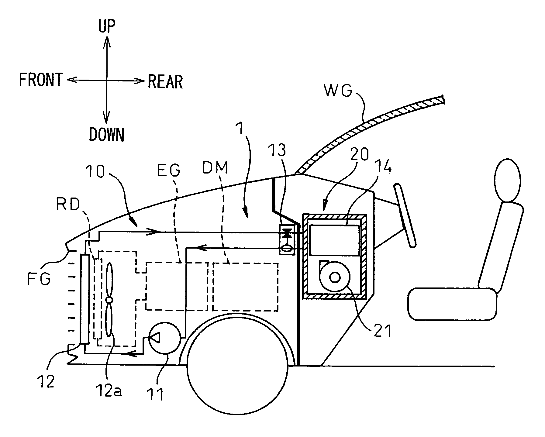
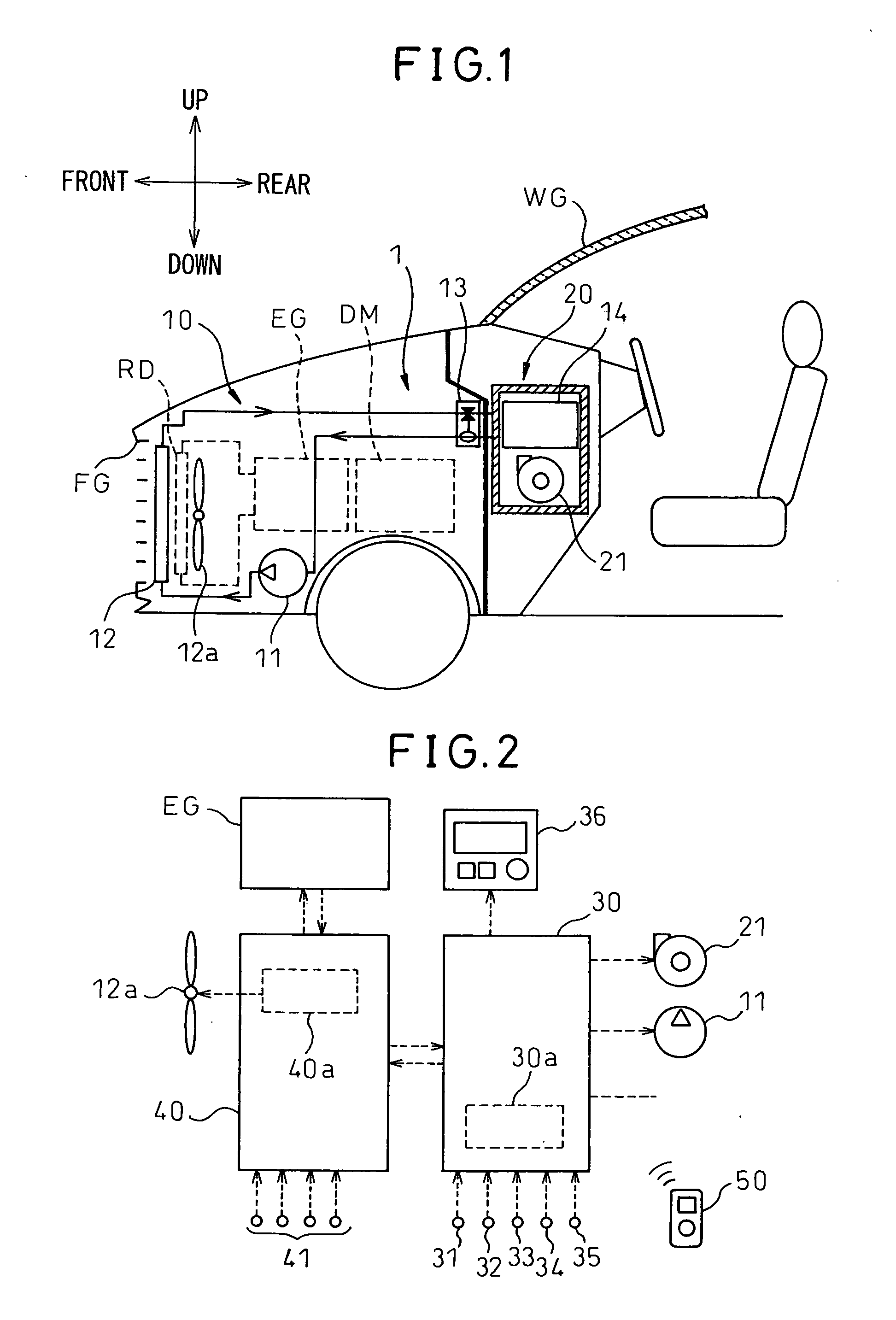
[0036]Using FIGS. 1 to 6, a first embodiment of the present invention will be explained. FIG. 1 is a view of the overall configuration of a vehicular air-conditioning system 1 using a vehicular refrigeration cycle apparatus 10 of the present embodiment. This vehicular air-conditioning system 1 is applied to a so-called hybrid car obtaining drive power for vehicle operation from an internal combustion engine (engine) EG and a drive-use electric motor DM. Note that, the arrows in the top, bottom, front, and back directions in FIG. 1 show the top, bottom, front, and back directions in the state mounting the vehicular air-conditioning system 1 in a vehicle.

[0037]The hybrid car of the present embodiment can operate or start the engine EG in accordance with the drive load etc. of the vehicle and switch between a driving state where it operates by obtaining drive power from both the engine EG and drive-use electric motor DM and a driving state where it operates by making the engine EG stop...

second embodiment

[0094]In the above-mentioned first embodiment, the example of the engine EG being stopped at the control step S42 was explained, but in the present embodiment, as shown in the flowchart of FIG. 7, step S42 is changed to S42′. Specifically, at step S42′ of the present embodiment, it is determined if the vehicle speed Vv which is detected by the vehicle speed sensor has become a predetermined reference vehicle speed KVv or less.

[0095]That is, at step S42′, it is determined if the vehicle is at a stop or is being driven at a reference vehicle speed KVv or less. When it is determined at step S42′ that the vehicle speed Vv is the reference vehicle speed KVv or less, the routine proceeds to step S43, while when it is determined that the vehicle speed Vv is not the reference vehicle speed KVv or less, the routine proceeds to step S47. Note that, the reference vehicle speed KVv is determined as an extremely low speed such as parking where almost no road noise is generated.

[0096]The rest of ...

third embodiment

[0098]In the above-explained embodiments, the example where the masking noise generating means was configured by the condenser-use blower 12a was explained, but in the present embodiment, the example where the masking noise generating means is configured by the evaporator-use blower 21 will be explained.

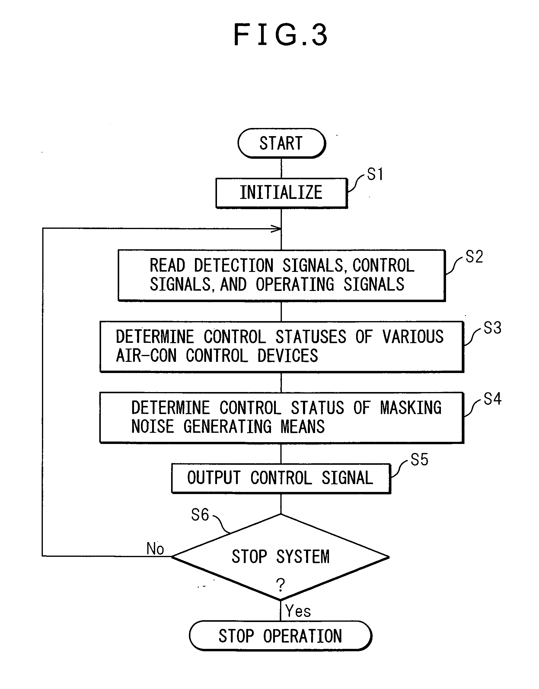
[0099]In this case, at step S44 shown in FIG. 4 of the first embodiment, it is sufficient to make the control voltage which is output to the evaporator-use blower 21 the highest value Hi and, at step S45, to make the control voltage which is output to the evaporator-use blower 21 an intermediate voltage Lo of an extent whereby the operating noise of the evaporator-use blower 21 becomes noise of a sufficient volume as the afore-mentioned masking noise. The rest of the overall configuration and control modes are the same as in the first embodiment.

[0100]Here, the operating noise of the evaporator-use blower 21 which blows air into the cabin is noise which persons inside the cabin are u...


PUM


Abstract

A vehicular refrigeration cycle apparatus where, at the time of startup before starting the operation of a compressor, the speed of a condenser-use blower which blows outside air toward the condenser is increased in accordance with the air-conditioning load. Due to this, the operating noise of the condenser-use blower familiar to the users becomes masking noise helping to prevent the operating noise of the compressor from being heard by the user and the unfamiliar operating noise of the compressor can be kept from being heard by the user.

Description

BACKGROUND OF THE INVENTION[0001]1. Field of the Invention[0002]The present invention relates to a vehicular refrigeration cycle apparatus which is provided with an electric compressor.[0003]2. Description of the Related Art[0004]In the past, there has been known a vehicular refrigeration cycle apparatus which is provided with an electric compressor. In this type of electric compressor, it is possible to adjust the speed of the electric motor so as to easily change the discharge flow.[0005]For example, in the vehicular refrigeration cycle apparatus used for the vehicular air-conditioning system of Japanese Patent Publication (A) No. 8-219071, at the time of startup of the electric compressor, to avoid liquid compression, the speed is kept low, then the speed is quickly increased so as to obtain a discharge flow in accordance with the air-conditioning heat load.SUMMARY OF THE INVENTION[0006]In this respect, when mounting a vehicular refrigeration cycle apparatus which is provided wit...

Claims


Application Information

Patent Timeline
IPC IPC(8): F25D19/00
CPCB60H1/3208B60H2001/3266B60H2001/3273B60H2001/3292F25B2500/12
Inventor TOMIYAMA, EIJIMIURA, NOBUHIRO
Owner DENSO CORP
Why Eureka
Try Eureka