Wireline-Adjustable Downhole Flow Control Devices and Methods for Using Same

a flow control device and wireline-adjustable technology, applied in the direction of survey, fluid removal, borehole/well accessories, etc., can solve the problems of insufficient setting, insufficient design or configuration of pre-set passive flow control devices for downhole adjustment, and uneven flow of oil between the formation and the wellbor

Active Publication Date: 2011-06-23
BAKER HUGHES INC
View PDF31 Cites 30 Cited by
  • Summary
  • Abstract
  • Description
  • Claims
  • Application Information

AI Technical Summary

Benefits of technology

[0007]In one aspect, a method of producing fluids from a wellbore that includes a production zone having a flow control device for controlling flow of fluid between a formation and the wellbore, the method in one embodiment may include: providing a tool having a sensor configured to provide measurements relating to a downhole property of interest, wherein the tool is configured to adjust flow from the flow control device; conveying the tool into the wellbore; and determining the parameter of interest using the tool; adjusting the flow through the flow control device with the tool at least in part in response to the determined parameter of interest.
[0008]In another embodiment, the method of controlling fluid from a formation may include: placing a flow control device at a selected location in the wellbore, the flow control device including a flow region and a setting device for adjusting the flow of the fluid through the flow region; conveying a tool into the wellbore, the tool being configured to move inside the flow control device, the tool including (i) a sensor configured to provide measurements relating to a downhole property of interest, and (ii) a latching device configured to couple to the setting device of the flow control

Problems solved by technology

Therefore, oil between the formation and the wellbore may not flow evenly through the various inflow control devices.
Such pre-set passive flow control devices are not designed or configured for downhole adjustments.
If it is determined that the flow of the fluid from particular flow co

Method used


Image

  • Wireline-Adjustable Downhole Flow Control Devices and Methods for Using Same
  • Wireline-Adjustable Downhole Flow Control Devices and Methods for Using Same
  • Wireline-Adjustable Downhole Flow Control Devices and Methods for Using Same

Examples


Embodiment Construction

[0020]The present disclosure relates to apparatus and methods for controlling flow of formation fluids in a well. The present disclosure provides certain exemplary drawings to describe certain embodiments of the apparatus and methods that are to be considered exemplification of the principles described herein and are not intended to limit the concepts and disclosure to the illustrated and described embodiments.

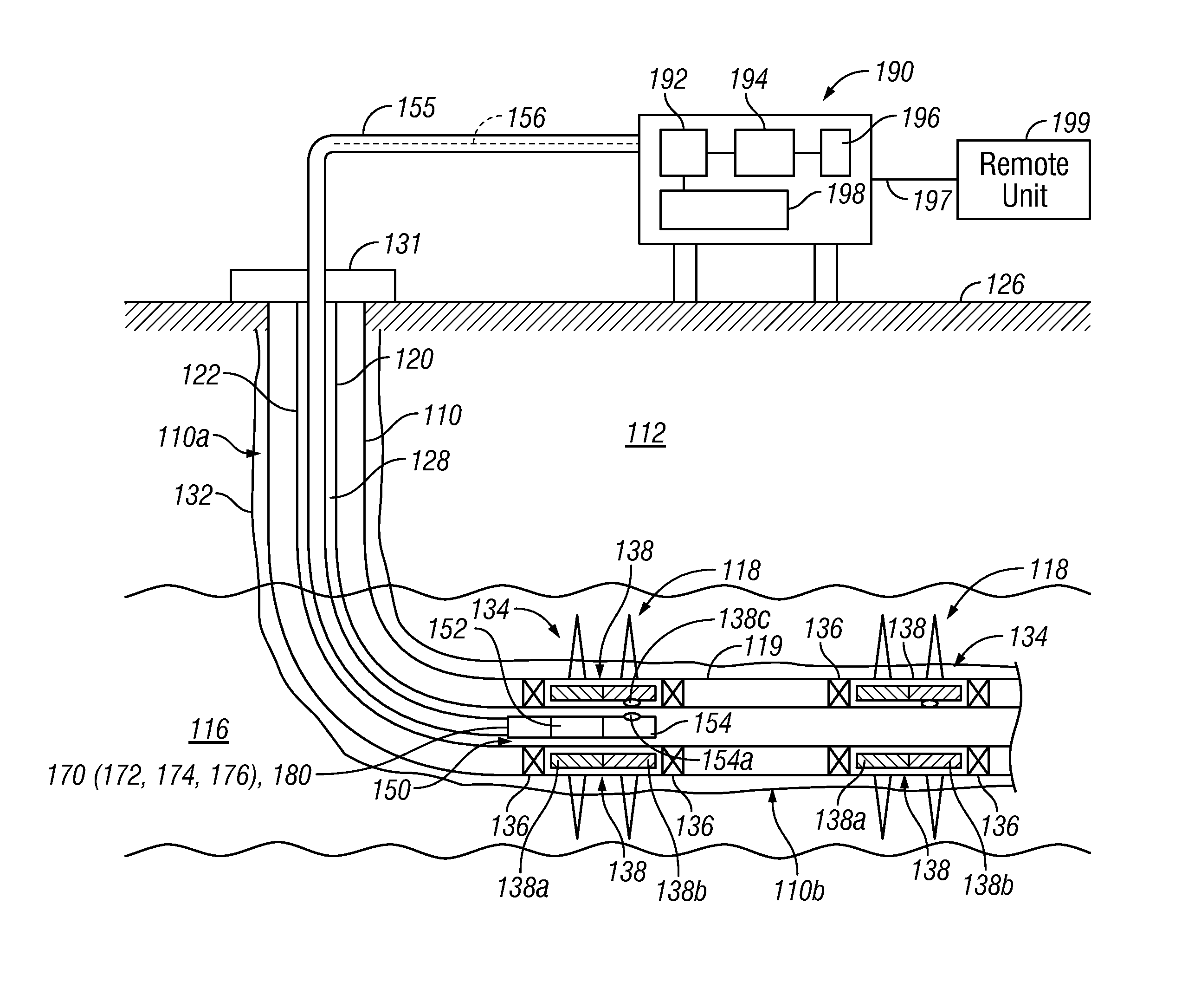
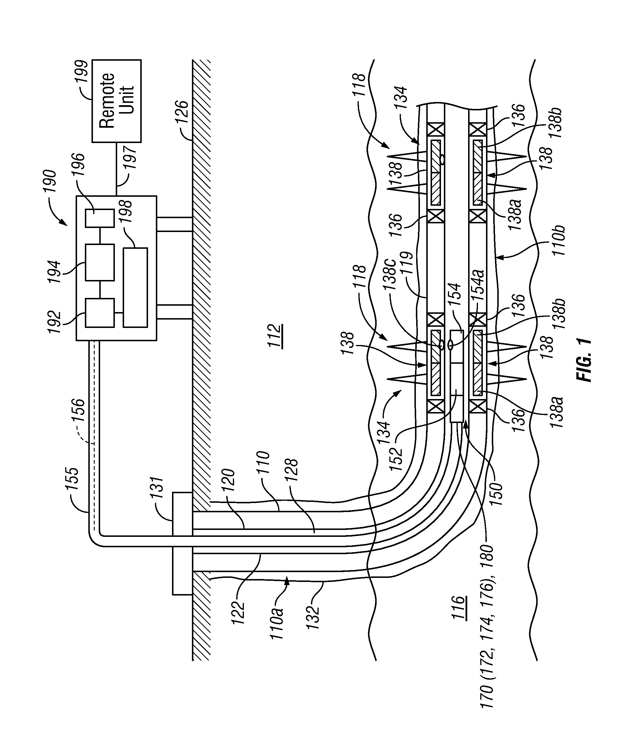
[0021]FIG. 1 is a schematic diagram of an exemplary production wellbore system 100 that includes a wellbore 110 drilled through an earth formation 112 and into a production zone or reservoir 116. The wellbore 110 is shown lined with a casing 113 having a number of perforations 118 that penetrate and extend into the formations production zone 116 so that production fluids may flow from the production zone 116 into the wellbore 110. The exemplary wellbore 110 is shown to include a vertical section 110a and a substantially horizontal section 110b. The wellbore 110 includes a prod...


PUM


Abstract

A method of producing fluids from a wellbore that has therein n adjustable flow control device for controlling flow of fluid between a formation and the wellbore may include: providing a tool having a sensor configured to provide measurements relating to a downhole property of interest, wherein the tool is configured to adjust flow from the flow control device; conveying the tool into the wellbore; determining the property of interest using the tool; and adjusting the flow through the flow control device with the tool at least in part in response to the determined parameter of interest. An apparatus for controlling fluid flow between a formation and a wellbore, according to one embodiment may include: a tool configured to be conveyed into a wellbore that contains at least one sensor for estimating a property of interest downhole and a latching device configured to couple to a flow control device in the wellbore to alter flow of the fluid through the flow control device.

Description

BACKGROUND OF THE DISCLOSURE[0001]1. Field of the Disclosure[0002]The disclosure relates generally to apparatus and methods for control of fluid flow from subterranean formations into a production string in a wellbore.[0003]2. Description of the Related Art[0004]Hydrocarbons such as oil and gas are recovered from a subterranean formation using a well or wellbore drilled into the formation. In some cases the wellbore is completed by placing a casing along the wellbore length and perforating the casing adjacent each production zone (hydrocarbon bearing zone) to extract fluids (such as oil and gas) from the associated a production zone. In other cases, the wellbore may be open hole, i.e. no casing. One or more inflow control devices are placed in the wellbore to control the flow of fluids into the wellbore. These flow control devices and production zones are generally separated by packers installed between them. Fluid from each production zone entering the wellbore is drawn into a tubu...

Claims


Application Information

Patent Timeline
IPC IPC(8): E21B43/12E21B47/00
CPCE21B47/10E21B34/14E21B43/12
Inventor O'MALLEY, EDWARD J.PETERSON, ELMER R.CORONADO, MARTIN P.GARCIA, LUIS A.
Owner BAKER HUGHES INC
Why Eureka
Try Eureka