Battery-Powered and Logic-Controlled Gas Lift Valve for Use in Wells and Methods of Using and Making Same

a logic-controlled, gas-powered technology, applied in the direction of borehole/well accessories, non-positive displacement pumps, thin material handling, etc., can solve the problems of insufficient downhole pressure, excessive introduction of injected gas to the selected locations, and general imprecise valve settings

Inactive Publication Date: 2011-07-28
BAKER HUGHES INC
View PDF8 Cites 10 Cited by
  • Summary
  • Abstract
  • Description
  • Claims
  • Application Information

AI Technical Summary

Benefits of technology

[0006]In one aspect, a downhole-adjustable flow control device is provided that in one embodiment includes an inflow control device with a flow-through region configured to receive formation fluid at an inflow region and discharge the received fluid at an outflow region. The inflow control device also includes a setting device configured to adjust the flow of the fluid through the flow-through region to a selected level, the setting device including a coupling member configured to be coupled to an external latching device adapted to move the coupling member to cause the setting device to alter the flow of the fluid to a desired level.
[0007]In another aspect, an apparatus for controlling flow is disclosed that in one embodiment may include a passive inflow control device configured to receive fluid from a formation and discharge the received fluid to an outflow region, a setting device configured to adjust flow of the fluid through the inflow control device, the setting device including a coupling member and a latching device configured to couple to the coupling member to operate the setting device to adjust the flow of the fluid through the inflow control device.
[0008]Examples of the more important features of the disclosure have been summarized rather broadly in order that detailed description thereof that follows may be better understood, and in order that the contributions to the art may be appreciated. There are, of course, additional features of the disclosure that will be described hereinafter and which will form the subject of the claims appended hereto.

Problems solved by technology

In some cases, the downhole pressure is not adequate to lift the formation fluid in the wellbore to the surface.
Such mechanically-set valves are generally imprecise and can result excessive introduction of the injected gas to the selected locations.

Method used


Image

  • Battery-Powered and Logic-Controlled Gas Lift Valve for Use in Wells and Methods of Using and Making Same
  • Battery-Powered and Logic-Controlled Gas Lift Valve for Use in Wells and Methods of Using and Making Same
  • Battery-Powered and Logic-Controlled Gas Lift Valve for Use in Wells and Methods of Using and Making Same

Examples


Embodiment Construction

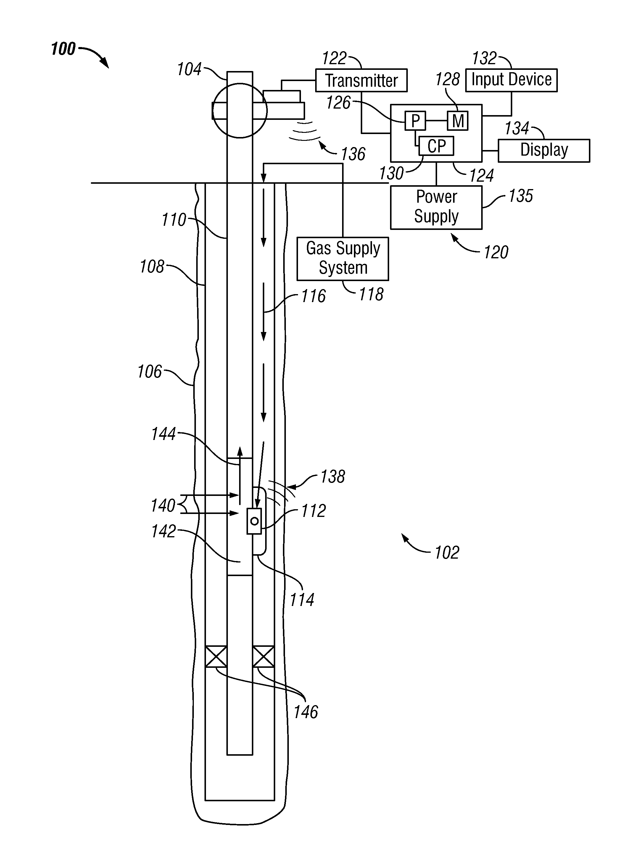
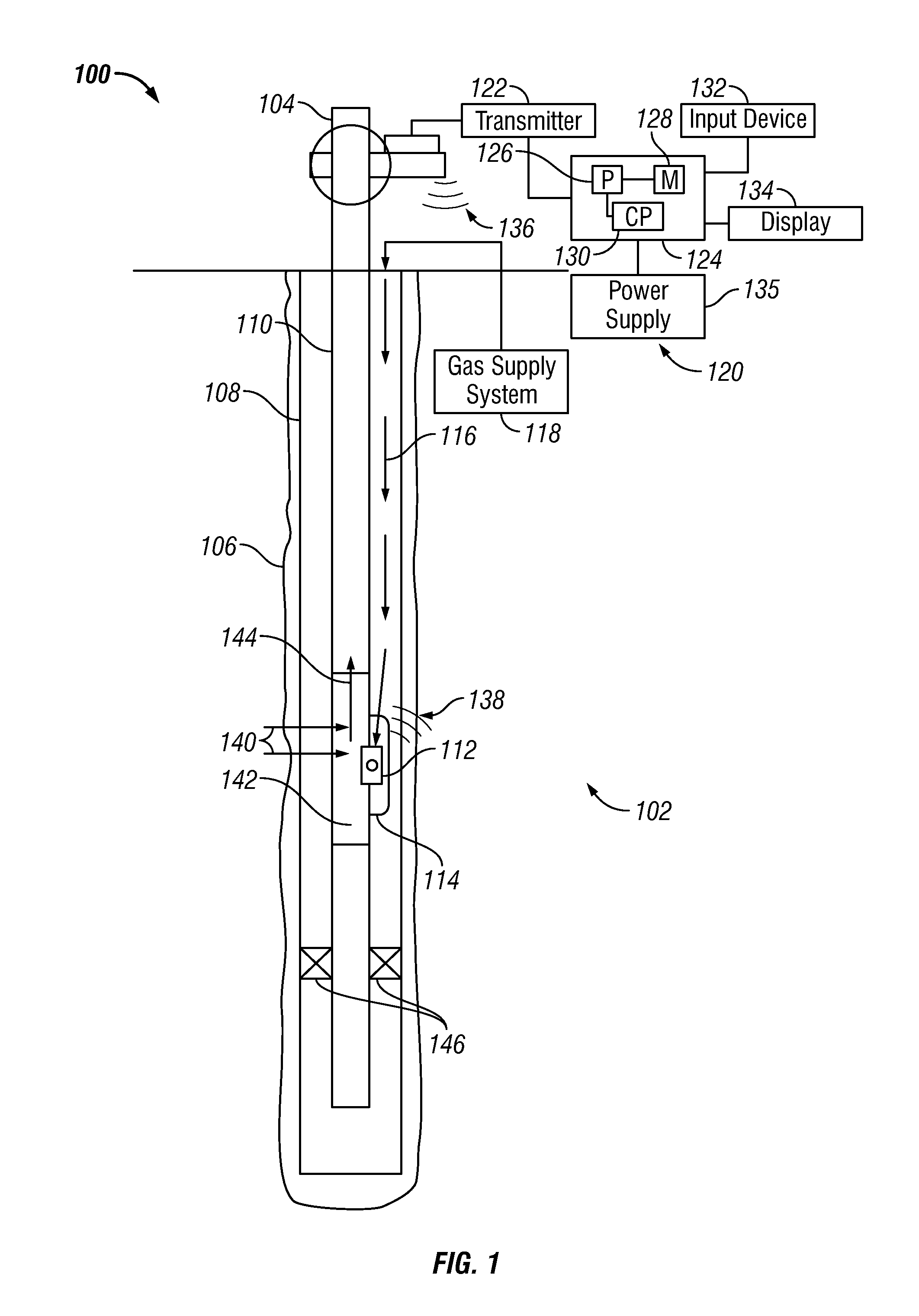
[0013]The present disclosure relates to apparatus and methods for controlling flow of formation fluids in a well. The present disclosure provides certain exemplary drawings to describe certain embodiments of the apparatus and methods that are to be considered exemplification of the principles described herein and are not intended to limit the concepts and disclosure to the illustrated and described embodiments.

[0014]FIG. 1 is a schematic illustration of an embodiment of a wellbore system 100 configured to extract hydrocarbons from a formation. The wellbore system 100 includes a flow control system 102, wellhead 104, wellbore 106 and casing 108. The flow control system 102 is configured to enhance flow of formation fluid from a formation adjacent to the wellbore 106 as it flows through the casing 108 into a mandrel or base pipe 110. The flow control system 102 includes a flow control device 112 located in a side pocket 114 of the base pipe 110. As discussed below, the flow control de...


PUM


Abstract

A flow control device is provided that in one embodiment includes a flow-through region configured to receive formation fluid at an inflow region and discharge the received fluid at an outflow region and a setting device configured to adjust the flow of the fluid through the flow-through region to a selected level. The setting device includes a coupling member configured to be coupled to an external latching device adapted to move the coupling member to cause the setting device to alter the flow of the fluid from the flow-through region to the selected level.

Description

BACKGROUND OF THE DISCLOSURE[0001]1. Field of the Disclosure[0002]The disclosure relates generally to gas lift apparatus for use in wells.[0003]2. Description of the Related Art[0004]Hydrocarbons such as oil and gas are recovered from a subterranean formation using a well or wellbore drilled into the formation. In some cases the wellbore is completed by placing a casing along the wellbore length and perforating the casing adjacent each production zone (hydrocarbon-bearing zone) to extract fluids (such as oil and gas) from the associated a production zone. In other cases, the wellbore may be open-hole, i.e. no casing. A production string is placed in the wellbore. The wellbore includes a tubing (also referred to as base pipe) and a number of flow control devices that enable the formation fluid to enter into the production tubing. In some cases, the downhole pressure is not adequate to lift the formation fluid in the wellbore to the surface. In such cases, artificial lift mechanisms a...

Claims


Application Information

Patent Timeline
Patent Type & Authority Applications(United States)
IPC IPC(8): E21B43/00F04F1/08
CPCF04F1/08E21B43/123Y10T137/2934
Inventor WILDMAN, SAMUEL L.KRITZLER, JAMES H.ATKINS, PAUL W.CHAVERS, RAYMOND D.BISSET, STEPHEN
Owner BAKER HUGHES INC
Why Eureka
Try Eureka