Organic light emitting display

a light-emitting display and organic technology, applied in the direction of thermoelectric device junction materials, electrical devices, semiconductor devices, etc., can solve the problems of shortening the life of the display, unable to achieve sufficient heat radiation, and large heat conduction distance between the radiation section and so as to achieve the promotion of thermal diffusion from the radiation section, shorten the heat conduction distance between the organic light-emitting elements and the radiation section, and increase the heat radiation efficiency

Active Publication Date: 2007-03-01
SAMSUNG DISPLAY CO LTD +1
View PDF6 Cites 12 Cited by
  • Summary
  • Abstract
  • Description
  • Claims
  • Application Information

AI Technical Summary

Benefits of technology

[0031] In the organic light emitting display according to an aspect of the invention, the heat conduction distance between the organic light emitting elements and the radiation section is shortened. As a result, thermal diffusion from the radiation section is promoted, and thus heat radiation efficiency is increased. Since the light emission efficiency of the organic light emitting elements is not deteriorated, extremely preferable advantages such as elongation of lifetime and reduction of power consumption of the organic light emitting display can be offered.
[0032] In the organic light emitting display according to another aspect of the invention, the heat conduction distance between the organic light emitting elements and the thermal conductor via the radiation section is shortened. As a result, thermal diffusion from the thermal conductor is further promoted, and thus heat radiation efficiency is further improved. Since the light emission efficiency of the organic light emitting elements is not deteriorated, extremely preferable advantages such as elongation of lifetime and reduction of power consumption of the organic light emitting display can be offered.
[0033] In the organic light emitting display according to another aspect of the invention, radiation means capable of achieving considerable heat radiation can be easily produced at a low cost without greatly changing the processes for manufacturing active elements, the organic light emitting elements and other components. Thus, extremely preferable advantages such as cost reduction of the organic light emitting display having high quality and high reliability can be offered.

Problems solved by technology

Generated heat generally deteriorates the light emission characteristic of the material of the organic light emitting layer OLE constituting the light emission mechanism, and shortens its lifetime.
However, in the organic light emitting displays having these structures in which a radiation section is simply disposed or affixed to the back of a substrate, when the substrate is constituted by a material having low thermal conductivity such as glass, the heat conduction distance between the radiation section and the organic light emitting elements, especially the organic light emitting layer, is large.
Therefore, sufficient radiation of heat cannot be achieved, and thus deterioration of the light emission characteristic of the organic light emitting layer constituting the light emitting mechanism is accelerated by heat generated at the time of turning on.
Moreover, the generated heat shortens the lifetime of the organic light emitting display.

Method used


Image

  • Organic light emitting display
  • Organic light emitting display
  • Organic light emitting display

Examples


first embodiment

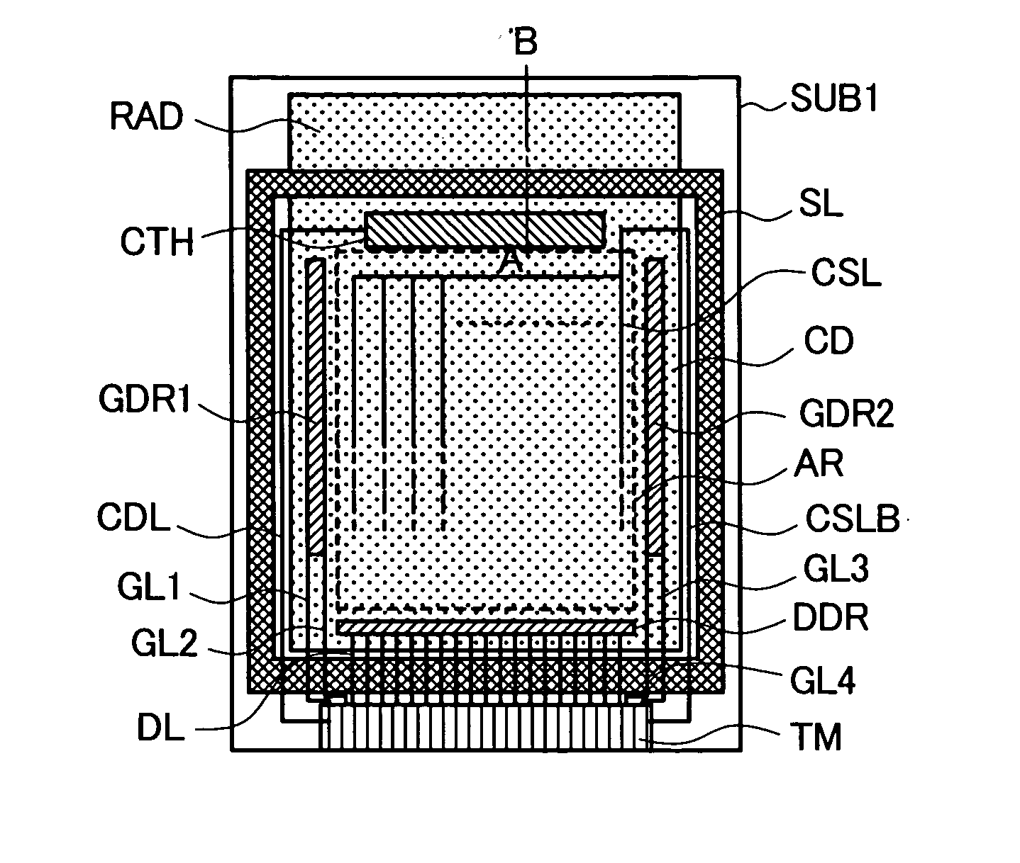
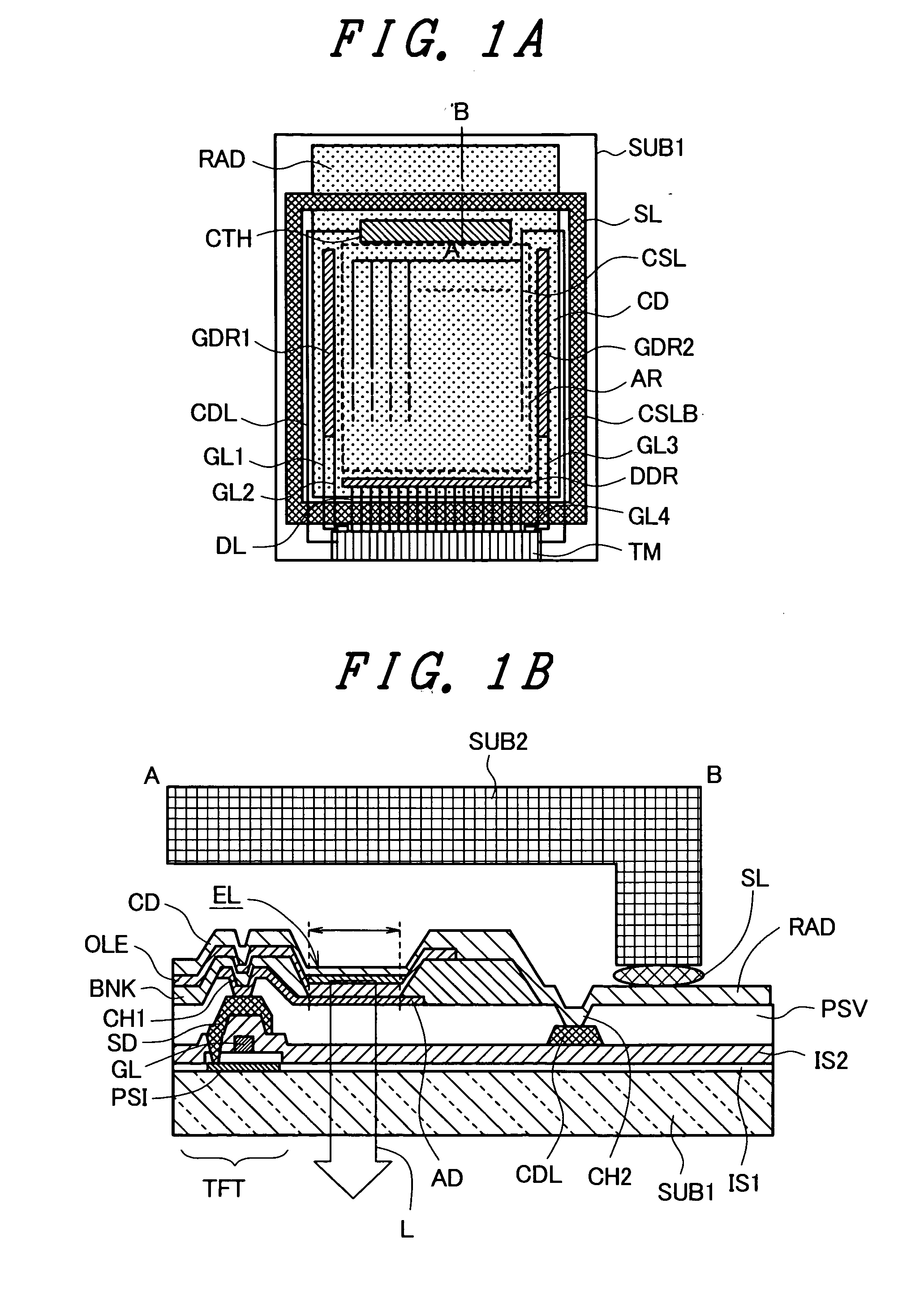
[0040]FIGS. 1A and 1B schematically illustrate a structure of an active-matrix-type organic light emitting display in a first embodiment according to the invention. FIG. 1A is a plan view showing an entire structure of a main part. FIG. 1B is an enlarged cross-sectional view showing a pixel and its vicinity taken along a line A-B in FIG. 1A. Reference numerals similar to those in FIGS. 5A and 5B are given to similar parts and components, and explanation of those is not repeated herein.

[0041] The organic light emitting display shown in FIGS. 1A and 1B includes a number of the organic light emitting elements EL extending throughout the surface of a display area AR. The end of the cathode CD as a second electrode, which is formed by aluminum material or metal material including aluminum, for example, and constitutes the organic light emitting elements EL, reaches outside the encapsulated area defined by the seal member SL at the end of the main substrate SUB1. This end forms a radiati...

second embodiment

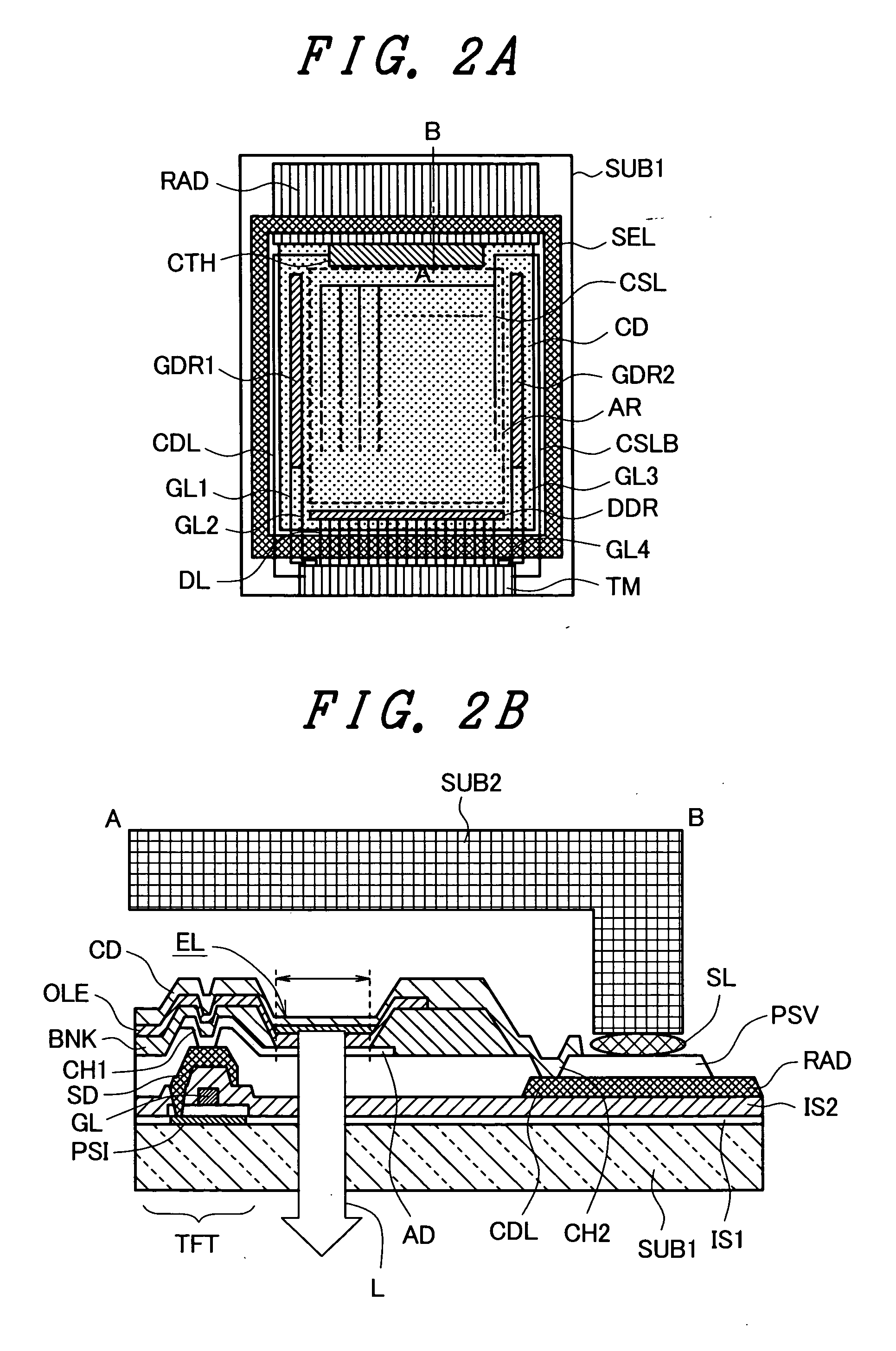
[0044]FIGS. 2A and 2B schematically illustrate a structure of an active-matrix-type organic light emitting display in a second embodiment according to the invention. FIG. 2A is a plan view showing an entire structure of a main part. FIG. 2B is an enlarged cross-sectional view showing a pixel and its vicinity taken along a line A-B in FIG. 2A. Reference numerals similar to those in FIGS. 5A and 5B are given to similar parts and components, and explanation of those is not repeated herein.

[0045] In the organic light emitting display shown in FIGS. 2A and 2B, apart of the cathode line CDL which is formed by aluminum material and disposed between the intermediate insulating layer IS2 of the main substrate SUB1 and the passivation layer PSV extends to the outside of the encapsulated area of the main substrate SUB1 on the intermediate insulating layer IS2. This part corresponds to the radiation section RAD formed integrally with the cathode line CDL. The radiation section RAD is made of t...

third embodiment

[0049]FIG. 3 schematically illustrates a structure of an active-matrix-type organic light emitting display in a third embodiment according to the invention. FIG. 3 is an enlarged cross-sectional view showing a pixel and its vicinity of a main part of the organic light emitting display. Reference numerals similar to those in FIGS. 2A and 2B are given to similar parts and components, and explanation of those is not repeated herein. The organic light emitting display shown in FIG. 3 has a thermal conductor HC covering the area from the surface of the radiation section RAD which is extended out of the encapsulated area of the main substrate SUB1 to the outer surface of the encapsulation glass substrate SUB2.

[0050] The thermal conductor HC is preferably a metal layer such as aluminum layer, copper layer, magnesium layer, and alloys of these materials. These metal layers can be formed by deposition, sputtering, CVD or other methods. Appropriate materials other than the metal layers invol...


PUM


Abstract

An organic light emitting display provided according to the invention maintains light emission efficiency and elongates its lifetime by radiating heat generated from organic light emitting elements to the outside of an encapsulated area. In the organic light emitting display, a part of a cathode is extended to the outside of the encapsulated area of a main substrate to form a radiation section integrally with the cathode. Heat generated from organic light emitting elements is diffused and radiated from the radiation section so that the heat can be discharged therefrom.

Description

CROSS-REFERENCE TO RELATED APPLICATIONS [0001] The disclosure of Japanese Patent Application No. 209503 / 2005 filed on Jul. 20, 2005 including the specification, drawings and abstract is incorporated herein by reference in its entirety. BACKGROUND [0002] 1. Field of the Invention [0003] The present invention relates to an organic light emitting display which includes an organic light emitting layer between a pair of electrodes and emits light from the organic light emitting layer by applying electric fields to the light emitting layer using the pair of the electrodes, and more particularly to an organic light emitting display which acquires long lifetime and high reliability by preventing deterioration of light emitting area efficiency of organic light emitting elements caused by heat generated from the organic light emitting layer which constitutes the light emitting area. [0004] 2. Description of Related Arts [0005] Currently, a flat-panel-type display such as a liquid crystal disp...

Claims


Application Information

Patent Timeline
Patent Type & Authority Applications(United States)
IPC IPC(8): H01L29/08
CPCH01L27/3276H01L51/5221H01L51/5237H01L51/529H01L2924/0002H01L2924/00H10K59/131H10K50/822H10K50/841H10K50/87
Inventor TOKUDA, NAOKISATO, TOSHIHIRO
Owner SAMSUNG DISPLAY CO LTD
Why Eureka
Try Eureka