

Water electrolysis apparatus
- Summary
- Abstract
- Description
- Claims
- Application Information
AI Technical Summary
Benefits of technology
Problems solved by technology
Method used
Image

Examples
first embodiment
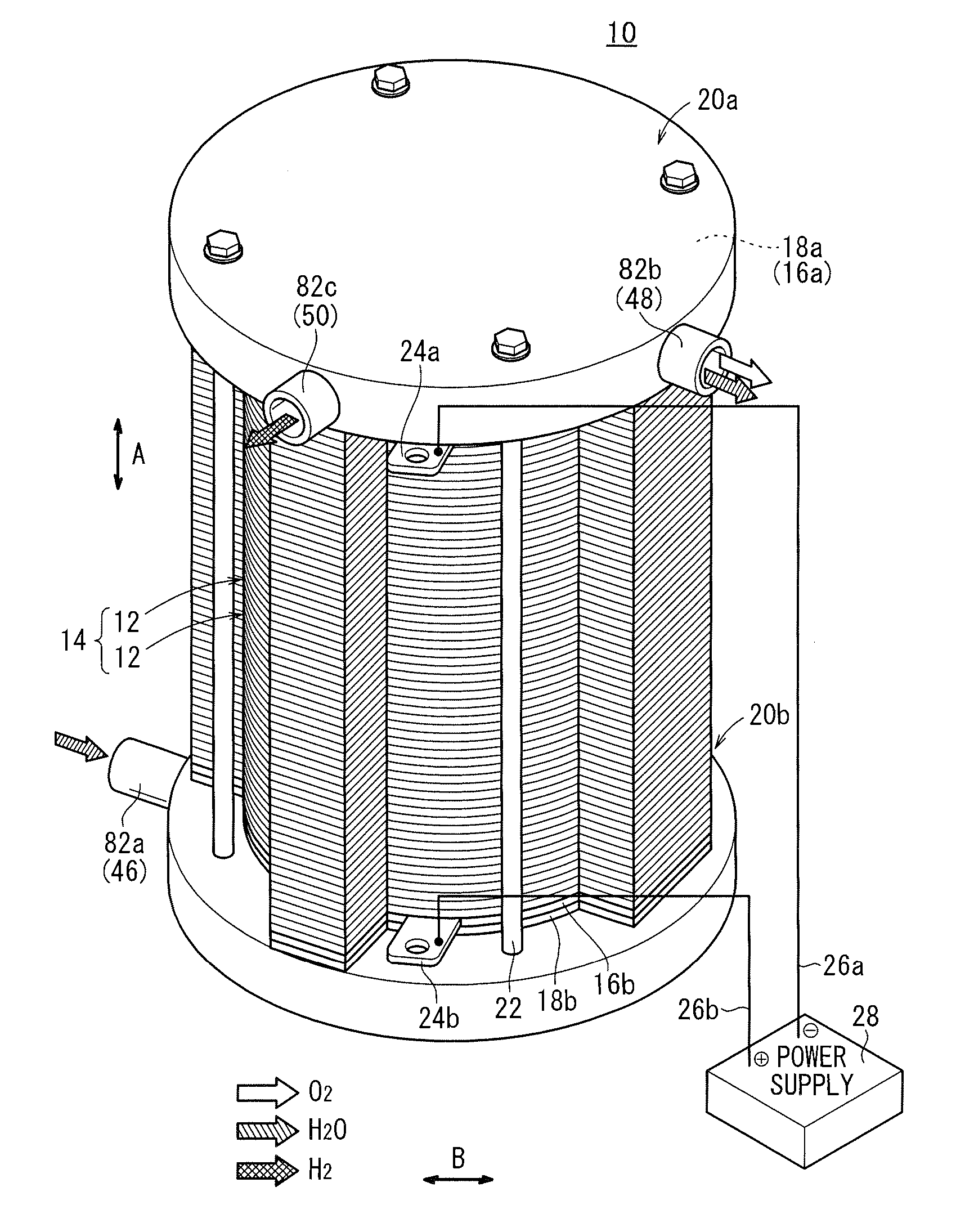
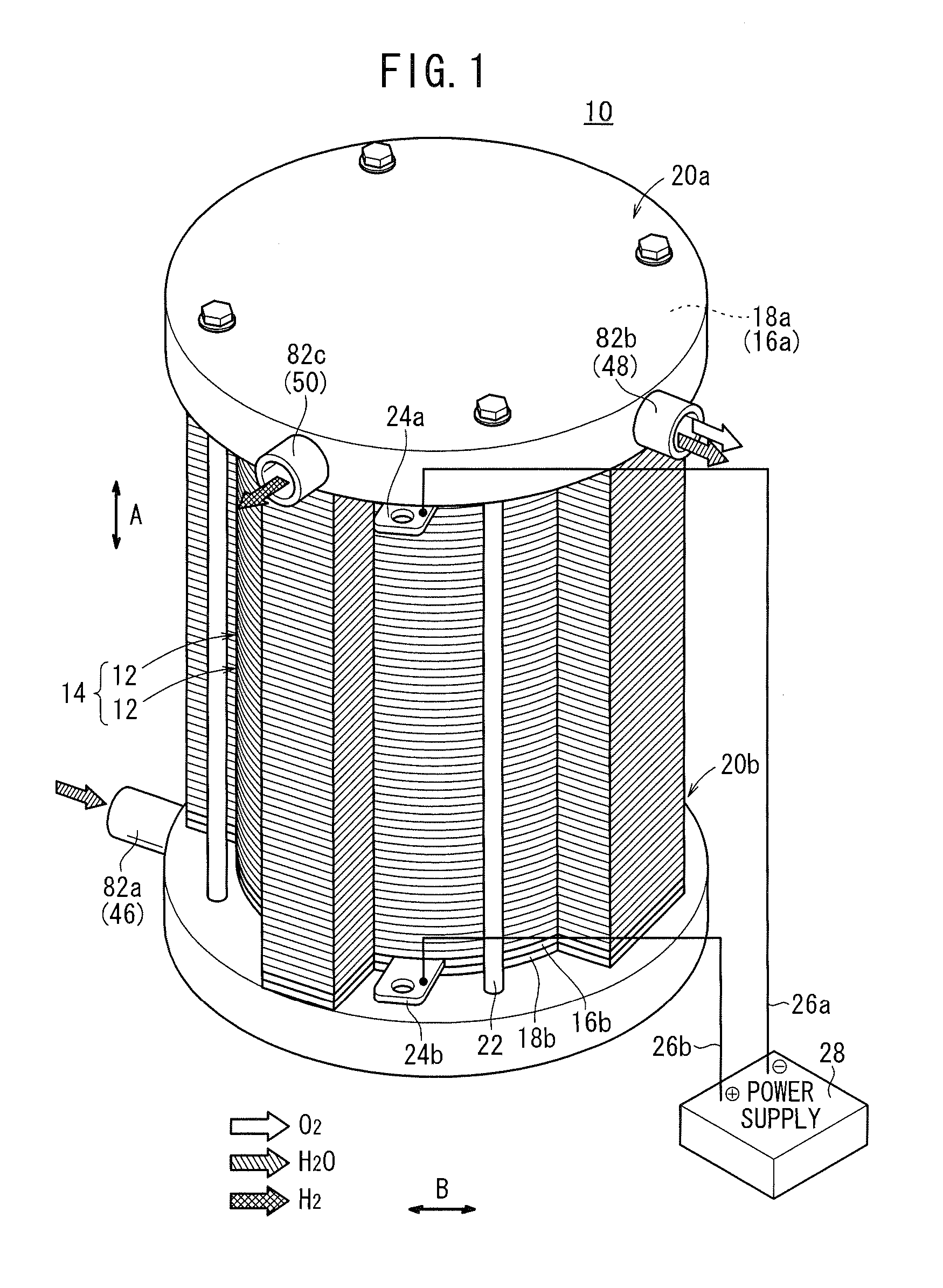
[0036]As shown in FIGS. 1 and 2, a water electrolysis apparatus 10 according to the present invention serves as a high-pressure hydrogen manufacturing apparatus, and includes a stack assembly 14 comprising a plurality of unit cells 12 stacked in a vertical direction indicated by the arrow A.
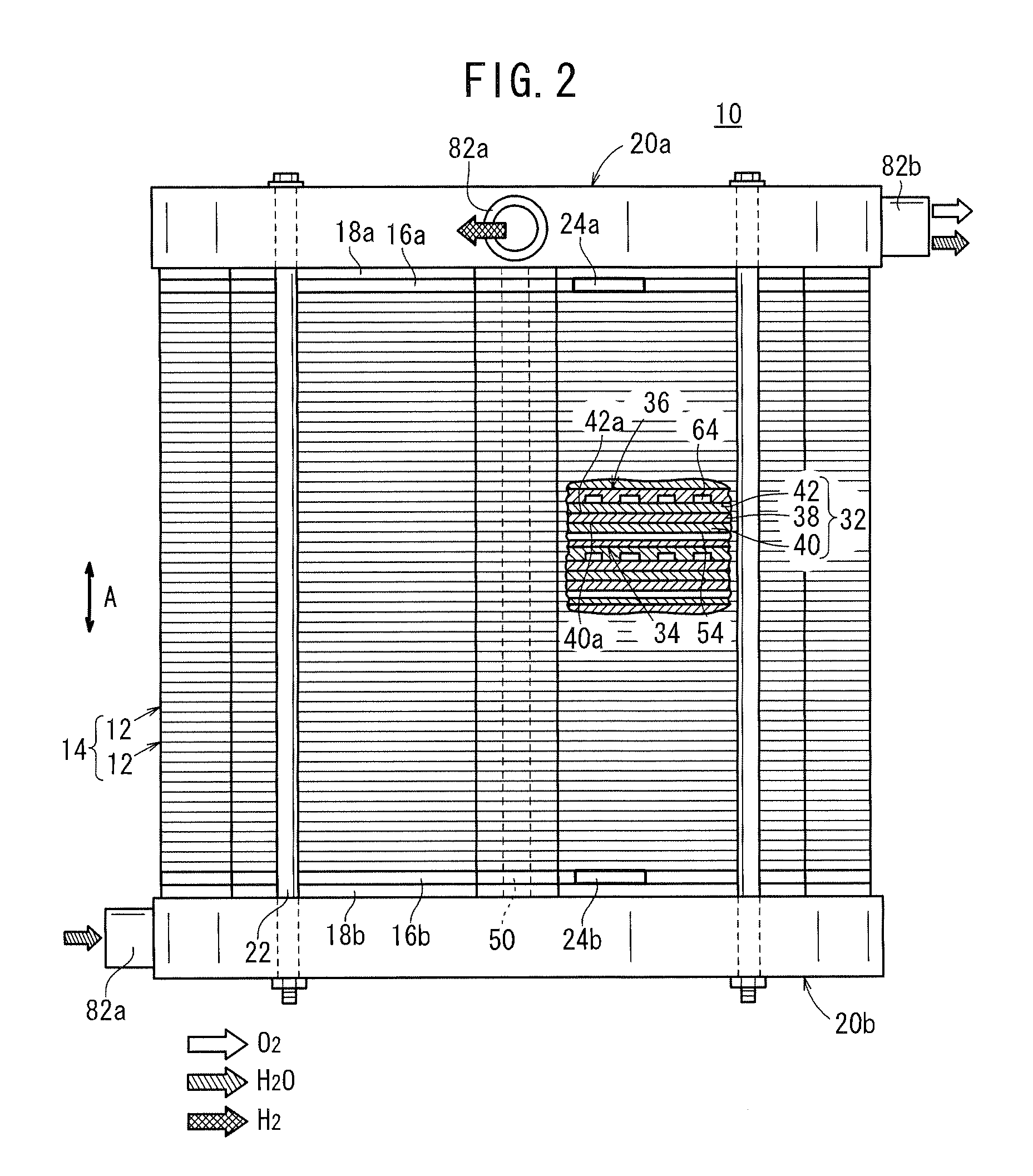
[0037]The water electrolysis apparatus 10 also includes a terminal plate 16a, an insulating plate 18a, and an end plate 20a which are mounted on an upper end of the stack assembly 14 upwardly in the order named, and a terminal plate 16b, an insulating plate 18b, and an end plate 20b which are mounted on a lower end of the stack assembly 14 downwardly in the order named. The unit cells 12, the terminal plates 16a, 16b, the insulating plates 18a, 18b, and the end plates 20a, 20b are of a disk shape.
[0038]The stack assembly 14, the terminal plates 16a, 16b, and the insulating plates 18a, 18b are fastened integrally together by the end plates 20a, 20b that are interconnected by four tie rods 22 exten...
second embodiment
[0071] the number of the inlet joint channels 98a of the unit cell 92 that is positioned vertically upward is greater than the number of the inlet joint channels 96a of the unit cell 92 that is positioned vertically downward.
[0072]Accordingly, the pressure loss in the inlet joint channels 98a of the upper unit cell 92 is less than the pressure loss in the inlet joint channels 96a of the lower unit cell 92. Thus, water flowing vertically upward through the water supply passages 46 also can be distributed equally into the water flow fields 54 of the unit cells 92 which are stacked together vertically.
[0073]Also, the number of the outlet joint channels 98b of the unit cell 92 that is positioned vertically upward is greater than the number of the outlet joint channels 96b of the unit cell 92 that is positioned vertically downward. Thus, water can be distributed equally into the water flow fields 54 of the unit cells 92 which are stacked together vertically.
[0074]The number of the inlet ...
third embodiment
[0079] the cross sectional area of the inlet joint channel 108a of the unit cell 102 that is positioned vertically upward is greater than that of the inlet joint channel 106a of the unit cell 102 that is positioned vertically downward.
[0080]Accordingly, the pressure loss in the inlet joint channels 108a of the upper unit cell 102 is less than the pressure loss in the inlet joint channels 106a of the lower unit cell 102. Thus, as in the second embodiment, water flowing vertically upward through the water supply passages 46 can be distributed equally into the water flow fields 54 of the unit cells 102 which are stacked together vertically.
[0081]FIG. 8 is an exploded perspective view of a water electrolysis apparatus 110 according to a fourth embodiment of the present invention. Those parts of the water electrolysis apparatus 110 which are identical to those of the water electrolysis apparatus 10 according to the first embodiment are denoted by identical reference characters and will n...
PUM
| Property | Measurement | Unit |
|---|---|---|
| Diameter | aaaaa | aaaaa |
| Shape | aaaaa | aaaaa |
| Area | aaaaa | aaaaa |
Abstract
Description
Claims
Application Information