Rotation sensor and direct current motor

Inactive Publication Date: 2011-06-23
NIPPON SOKEN +1
View PDF3 Cites 26 Cited by
  • Summary
  • Abstract
  • Description
  • Claims
  • Application Information

AI Technical Summary

Benefits of technology

[0011]In view of the above, it is an object of the present invention to provide a rotation sensor for accurately detecting a rotation state of a direct current motor regar

Problems solved by technology

However, the use of the large-scale sensor in a vehicle increases the size, weight, and cost of the vehicle.
However, this method based on the surge pulse has the following disadvantage.
Therefore, it becomes more difficult to detect the surge

Method used


Image

  • Rotation sensor and direct current motor
  • Rotation sensor and direct current motor
  • Rotation sensor and direct current motor

Examples


first embodiment

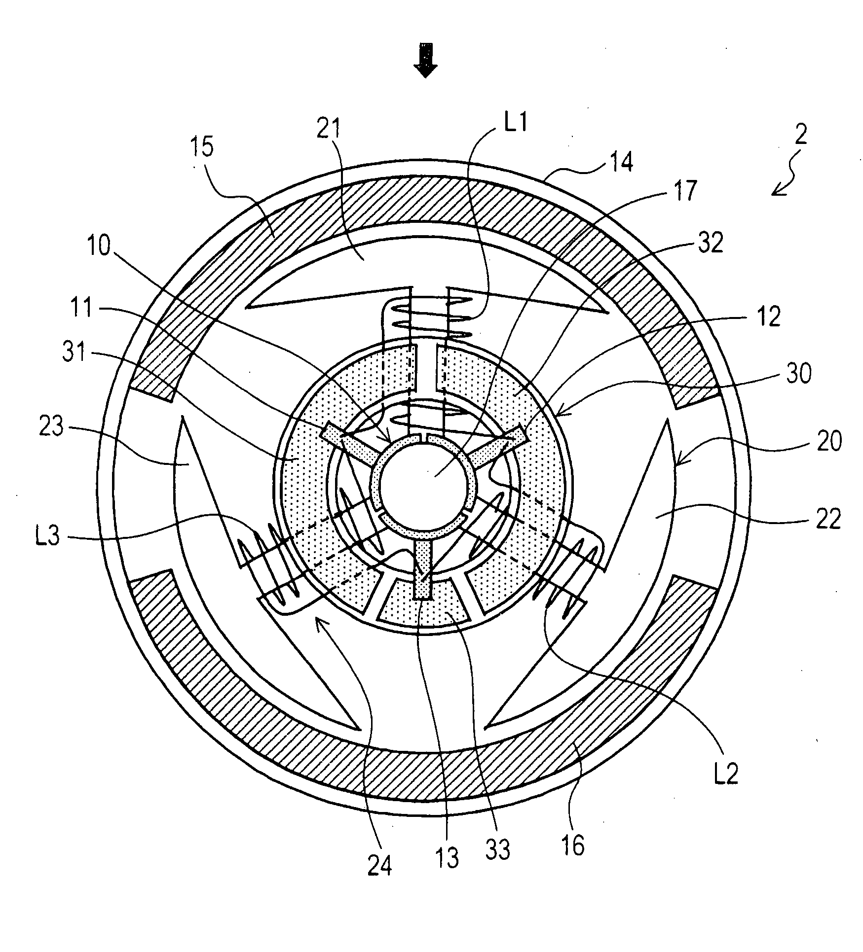
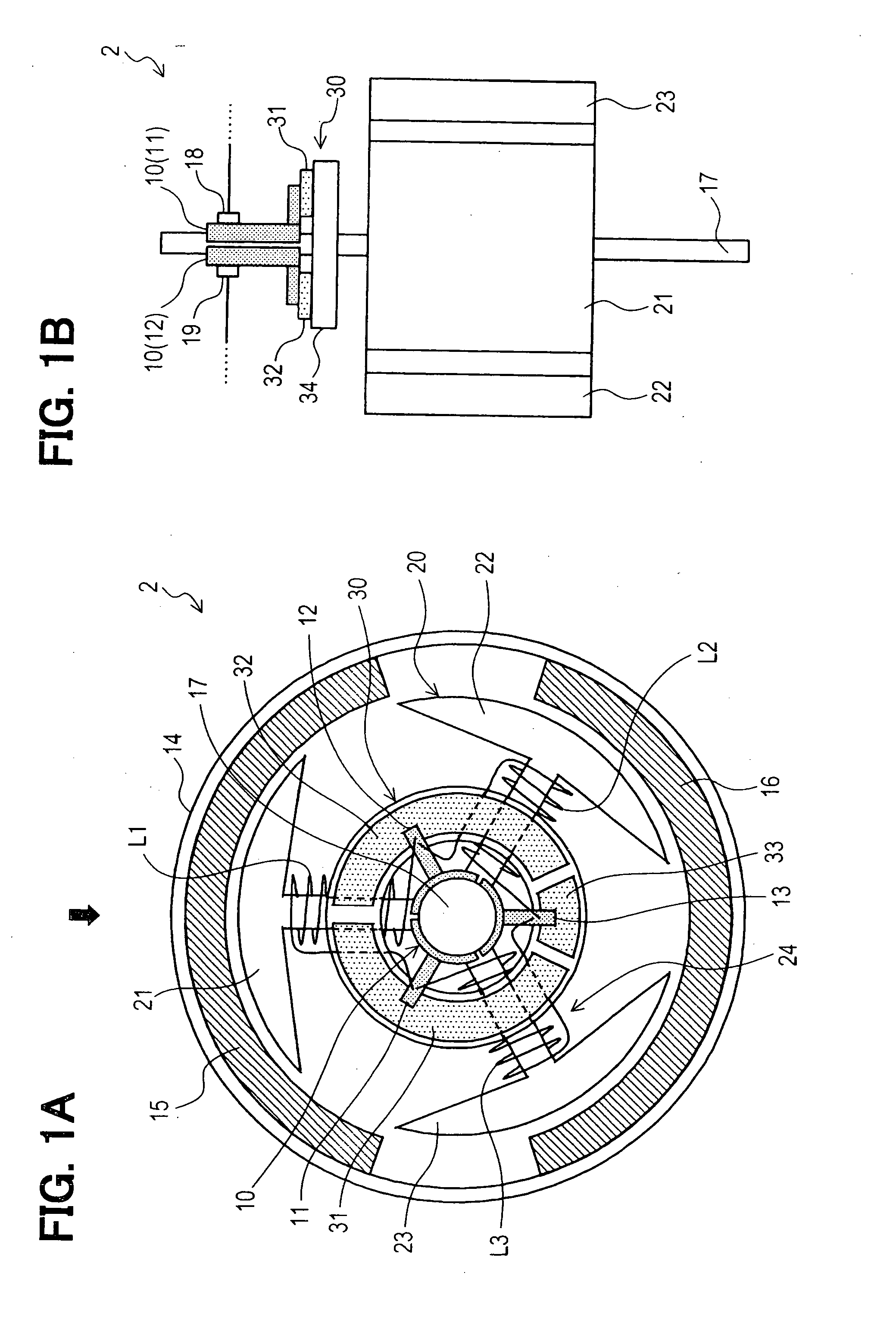
[0035]A motor 2 according to a first embodiment of the present invention is described below with reference to FIGS. 1A and 1B. FIG. 1A is a plan view of the motor 2. FIG. 1B is a front view of the motor 2 viewed from a direction indicated by an arrow in FIG. 1A. For the sake of simplicity, a housing 14 and magnets 15, 16 of the motor 2 are omitted in FIG. 1A, and a pair of brushes 18, 19 of the motor 2 is omitted in FIG. 1B.

[0036]The motor 2 includes a housing 14 and a rotor core 20 held in the housing 14. The rotor core 20 is fixed to a rotating shaft 17 that is located in a center axis of the housing 14. The rotor core 20 rotates with the rotating shaft 17.

[0037]The housing 14 is made of a soft magnetic material (i.e., yoke) and has a substantially cylindrical shape. Two field magnets 15, 16 are fixed to an inner surface of the housing 14 in such a manner that the field magnets 15, 16 are located radially opposite to each other. Each of the magnets 15, 16 is a permanent magnet. A ...

second embodiment

[0128]A rotation sensor according to a second embodiment of the present invention is described below with reference to FIGS. 11-15B.

[0129]Although not shown in the drawings, the rotation sensor according to the second embodiment has almost the same structure as the rotation sensor 1, shown in FIG. 3, of the first embodiment. The second embodiment differs from the first embodiment in that a motor 60 having a motor circuit shown in FIG. 12 is used instead of the motor 2. The motor 60 differs from the motor 2 in that a ring varistor 50 shown in FIG. 11 is used instead of the ring varistor 30, a signal processor 71 instead of the signal processor 27 has two comparing sections 73, 74 and two threshold setting sections 75, 76 with different threshold values, two rotation pulses are generated based on comparison results outputted from the comparing sections 73, 74, and a rotation detector 72 instead of the rotation detector 7 detects a rotation angle, a rotation direction, a rotation speed...


PUM


Abstract

A direct current motor includes an armature coil having at least three phase coils, a commutator having multiple commutator segments connected to the armature coil, a pair of brushes in slidable contact with the commutator to supply power to the phase coils through the commutator, a rotation shaft, and a ring varistor coaxially fixed to the rotation shaft and having a ring-shaped varistor body and multiple electrodes that are circumferentially arranged on a surface of the varistor body. Each commutator segment is connected to a corresponding electrode of the ring varistor. The electrodes of the ring varistor are paired to form electrode pairs. Each electrode pair includes any two of the electrodes. A capacitance of one electrode pair is different from a capacitance of another electrode pair.

Description

CROSS REFERENCE TO RELATED APPLICATION[0001]This application is based on and incorporates herein by reference Japanese Patent Application No. 2009-286483 filed on Dec. 17, 2009.FIELD OF THE INVENTION[0002]The present invention relates to a rotation sensor for detecting a rotation state of a direct current motor and also relates to the direct current motor.BACKGROUND OF THE INVENTION[0003]A brushed direct current motor (hereinafter called the “DC motor”) has been widely used in a vehicle. For example, the DC motor is used in an air-mixing damper and a mode damper of an air conditioner of a vehicle.. The air-mixing damper allows temperature adjusting, and the mode damper allows air outlet switching. There is a need to accurately detect a rotation state (e.g., rotation angle, rotation direction, rotation speed) of the DC motor in order to accurately control such dampers.[0004]In a conventional method, a rotation state of a DC motor is detected by using a large-scale sensor such as a ro...

Claims


Application Information

Patent Timeline
IPC IPC(8): H02K11/00
CPCH02K23/66
Inventor TANAKA, KENFUKAGAWA, YASUHIROTOUGE, MASARU
Owner NIPPON SOKEN
Why Eureka
Try Eureka