System and method for combining laser arrays for digital outputs

a laser array and laser array technology, applied in semiconductor lasers, lighting and heating apparatuses, instruments, etc., can solve the problems of inefficient methods and systems, and inability to achieve the effect of combining laser arrays and light sources

Active Publication Date: 2011-06-23
LUMENTUM OPERATIONS LLC
View PDF65 Cites 58 Cited by
  • Summary
  • Abstract
  • Description
  • Claims
  • Application Information

AI Technical Summary

Problems solved by technology

Light has been used to create color intensity for displays, but the methods and the systems used are inefficient, bulky, and produce dim or non-scalable results.
The use of lasers as a light source also has the drawback of a scintillation effect, which produces light and dark areas of the spot or pixel.
Producing correct color semiconductor laser sources has only been possible with edge emitting semiconductor laser devices.
However, this type of laser device is not conducive to photo-lithographically arrayed designs since they must be cleaved on edge to produce the cavity for lasing.
Consequently, this has limited laser display sources to single devices or mechanically ganged single devices.
While VCSELs offer advantages over edge-emitting lasers, VCSELs have not found use in imaging systems because VCSELs have only recently been created that are capable of producing the green output wavelength.
While green output VCSELs have been created, these devices had extreme power requirements and a number of reliability issues.
In fact, the blue VCSEL has only been commercially available for a few years.
However, all of these methods are heavily dependent on mechanical mirrors.
These sources are generally colors filtered out of a white light source such as a costly projector lamp that uses a great amount of wasted energy that is not in the filtered wavelength.
All this excess wasted energy produces large amounts of heat which make the system size much larger and more expensive in order to manage the thermal problem created by the excess heat.
All of these technologies require expensive, bulky, energy wasting technology and / or rely on mechanical mirrors, arrays of mirrors, and expensive supporting apparatuses to function.

Method used


Image

  • System and method for combining laser arrays for digital outputs
  • System and method for combining laser arrays for digital outputs
  • System and method for combining laser arrays for digital outputs

Examples


Embodiment Construction

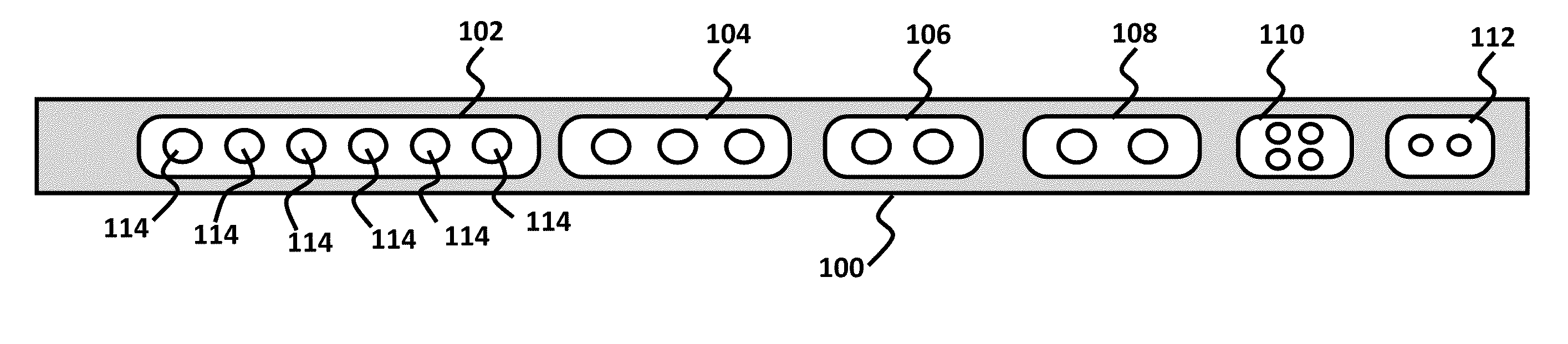
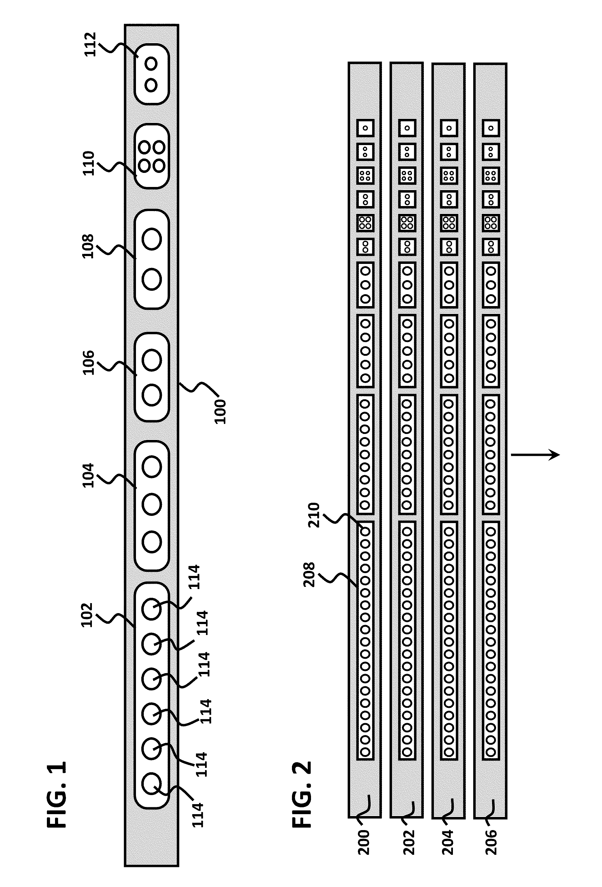
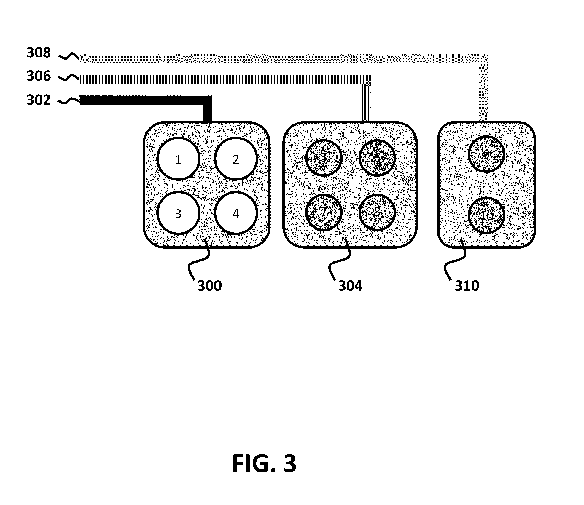
[0030]Embodiments comprise a device that can efficiently produce a highly resolved intensity profile that can be easily switched to various specific configurations with binary strings. The binary strings define output intensities that are combined to form the color for a pixel. Arraying these devices allows an image line of pixels to be efficiently produced without gross scintillation effects. Non-coherent output is desirable in this application as it reduces scintillation effects on the screen or final image.

[0031]Embodiments that use VCSELs allow for a higher bandwidth due to the high power and frequency response of VCSELs. This further enables brighter images due to the combination of the output from many VCSEL elements forming the color for a single pixel. As will be further described below, embodiments also result in smaller fabrication sizes due to the photo-lithographically defined features of laser devices such as VCSELs and VECSELs. Embodiments also use less energy because ...


PUM


Abstract

Embodiments comprise a device that can efficiently produce a highly resolved intensity profile that can be easily switched to various specific configurations with binary word strings defining output intensities that after summation will be combined to form a single colors intensity depth. Arraying these devices allows an image line of single color pixels to be efficiently produced without gross scintillation effects. The non-coherent output is desirable in this application as it reduces scintillation effects on the screen or final image.

Description

CROSS-REFERENCES TO RELATED APPLICATIONS[0001]This application claims priority to U.S. Provisional Application No. 61 / 288,269, filed Dec. 19, 2009, and which is incorporated by reference in its entirety.BRIEF DESCRIPTION OF THE INVENTION[0002]Embodiments comprise a device that can efficiently produce a highly resolved intensity profile that can be easily switched to various specific configurations with binary strings defining output intensities. The output intensities from laser arrays are combined to form a single color or wavelength. Arraying these devices allows an image line of single color pixels to be efficiently produced without gross scintillation effects. Non-coherent output is desirable in this application as it reduces scintillation effects on the screen or final image.STATEMENTS AS TO THE RIGHTS TO INVENTIONS MADE UNDER FEDERALLY SPONSORED RESEARCH OR DEVELOPMENT[0003]Not applicable.REFERENCE TO A “SEQUENCE LISTING,” A TABLE, OR A COMPUTER PROGRAM LISTING APPENDIX SUBMIT...

Claims


Application Information

Patent Timeline
Patent Type & Authority Applications(United States)
IPC IPC(8): H05B37/02
CPCF21K9/00H01S5/4012G02B6/4214
Inventor JOSEPH, JOHN R.WIEDEMANN, RUDOLF A.
Owner LUMENTUM OPERATIONS LLC
Why Eureka
Try Eureka