Log periodic antenna

Inactive Publication Date: 2011-06-23
ELECTRONICS & TELECOMM RES INST
View PDF4 Cites 12 Cited by
  • Summary
  • Abstract
  • Description
  • Claims
  • Application Information

AI Technical Summary

Benefits of technology

[0014]An embodiment of the present invention is directed to a log periodic antenna hav

Problems solved by technology

Therefore, any attempt to reduce the length of the dipole radiation elements and the overall size is limited.
These approaches may reduce the length of dipole radiation elements, but cannot increase the gain.
This

Method used


Image

  • Log periodic antenna
  • Log periodic antenna
  • Log periodic antenna

Examples


Embodiment Construction

[0040]Exemplary embodiments of the present invention will be described below in more detail with reference to the accompanying drawings. The present invention may, however, be embodied in different forms and should not be constructed as limited to the embodiments set forth herein. Rather, these embodiments are provided so that this disclosure will be thorough and complete, and will fully convey the scope of the present invention to those skilled in the art. Throughout the disclosure, like reference numerals refer to like parts throughout the various figures and embodiments of the present invention.

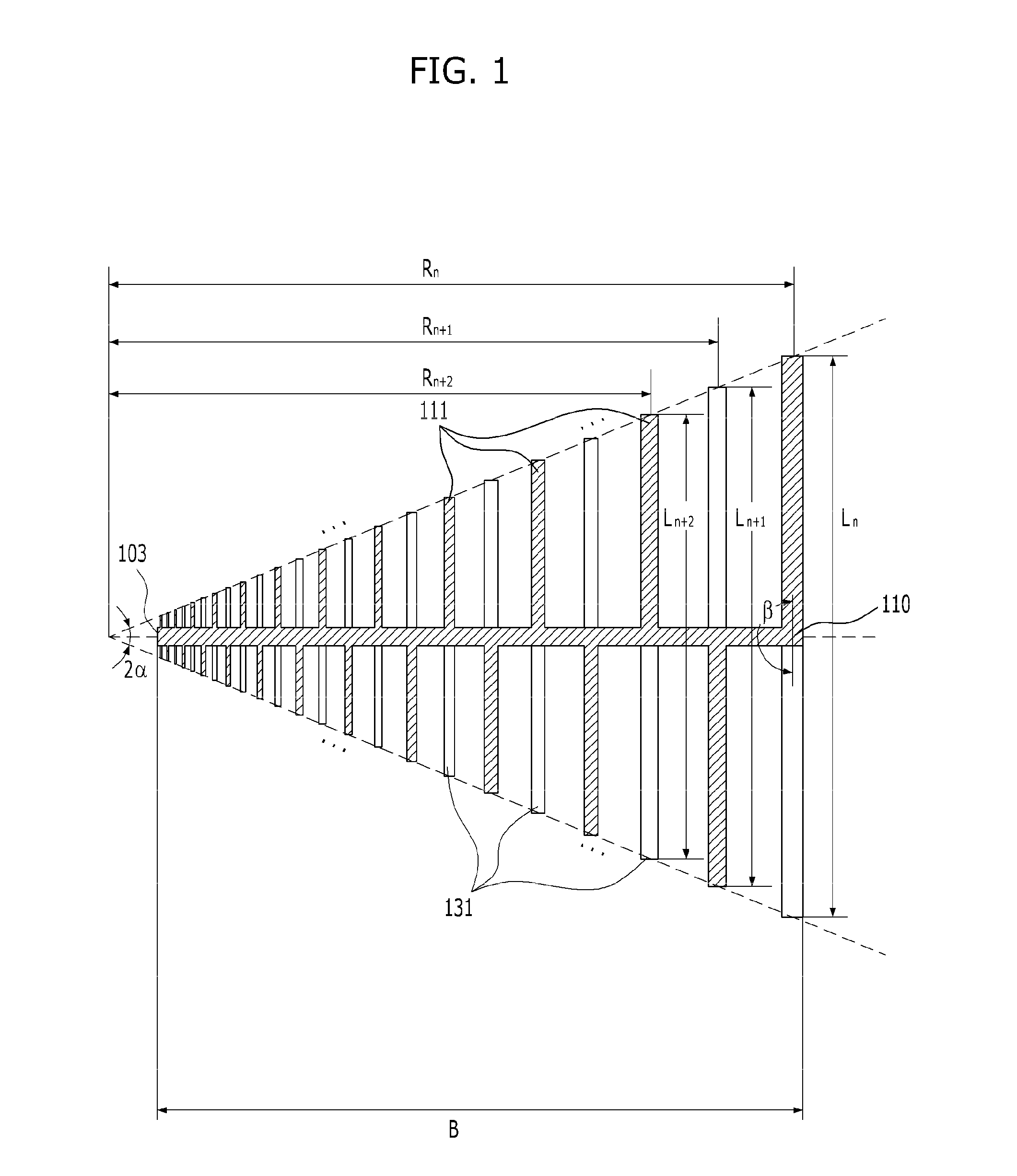
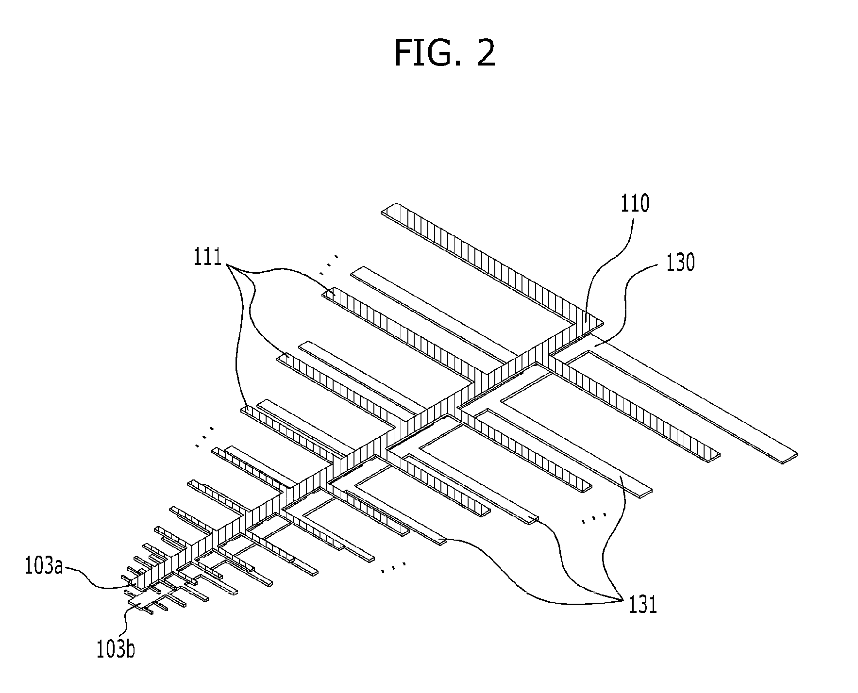
[0041]FIG. 1 is a top view of a conventional log periodic dipole antenna, and FIG. 2 is a perspective view of the conventional log periodic dipole antenna illustrated in FIG. 1.

[0042]Referring to FIG. 2, the conventional log periodic dipole antenna includes parallel transmission lines consisting of first and second transmission lines 110 and 130, a first feed terminal 103a formed on one si...


PUM


Abstract

A log periodic antenna includes first and second transmission lines parallel with each other; and a plurality of broadband radiation elements having first sides electrically connected to the first and second transmission lines, a predetermined angle being defined between the first sides of the broadband radiation elements and the first and second transmission lines, and second sides not electrically connected with the first and second transmission lines, the second sides having radiation surfaces larger than radiation surfaces of the first sides. A plurality of broadband radiation elements electrically connected with the first transmission line and a plurality of broadband radiation elements electrically connected with the second transmission line are positioned to face each other with reference to the first and second transmission lines.

Description

CROSS-REFERENCE(S) TO RELATED APPLICATIONS[0001]The present application claims priority of Korean Patent Application No. 10-2009-0128521, filed on Dec. 21, 2009, which is incorporated herein by reference in its entirety.BACKGROUND OF THE INVENTION[0002]1. Field of the Invention[0003]Exemplary embodiments of the present invention relate to a log periodic antenna; and, more particularly, to a log periodic antenna having a reduced beam width of the H-surface radiation pattern and high-gain directivity.[0004]2. Description of Related Art[0005]In general, an antenna is configured to convert electric signals, which are described in terms of voltage / current, into electromagnetic waves, which are described in terms of electric / magnetic fields, and vice versa. Antennas include dipole antennas, monopole antennas, patch antennas, horn antennas, parabolic antennas, helical antennas, slot antennas, log periodic antennas, etc.[0006]The log periodic antennas have broadband characteristics and a su...

Claims


Application Information

Patent Timeline
IPC IPC(8): H01Q11/10
CPCH01Q11/10H01Q11/06H01Q9/16H01Q9/40H01Q9/42
Inventor RO, HAENG-SOOKPARK, GWANG-MOONKIM, SANG-TAELEE, SEONG-YUNSUK, MI-KYUNGKANG, HEUNG-YONGCHOI, YONG-SEOK
Owner ELECTRONICS & TELECOMM RES INST
Why Eureka
Try Eureka