Laser beam scanner

a laser scanner and laser beam technology, applied in the field of laser beam scanners, can solve the problems of large beam detector and mounting space, large capacitance of sensing elements, and deterioration of response, so as to reduce the capacitance of light-receiving surfaces, reduce the effect of positional variations in sensitivity of light-receiving surfaces and reduce the effect of capacitan

Inactive Publication Date: 2007-01-02
BROTHER KOGYO KK
View PDF7 Cites 4 Cited by
  • Summary
  • Abstract
  • Description
  • Claims
  • Application Information

AI Technical Summary

Benefits of technology

[0016]Accordingly, a light-receiving surface of the detector can be made smaller. As a result, the capacitance of the light-receiving surface can be reduced and its response can be improved. In addition, positional variations in sensitivity of the light-receiving surface can be minimized. Thus, a lag of the scan start timing of each laser beam can be reduced.
[0017]Further, as the light-receiving surface becomes smaller, the beam detector

Problems solved by technology

However, as the light-receiving surface is increased, capacitance of the sensing element increases and its response deteriorates.
Another problem is that the large light-

Method used


Image

  • Laser beam scanner
  • Laser beam scanner
  • Laser beam scanner

Examples


first embodiment

[0031]a laser beam scanner according to the invention will be described in conjunction with the attached drawings. In the following exemplary embodiments, a laser beam scanner implementing the invention is used in a laser beam printer.

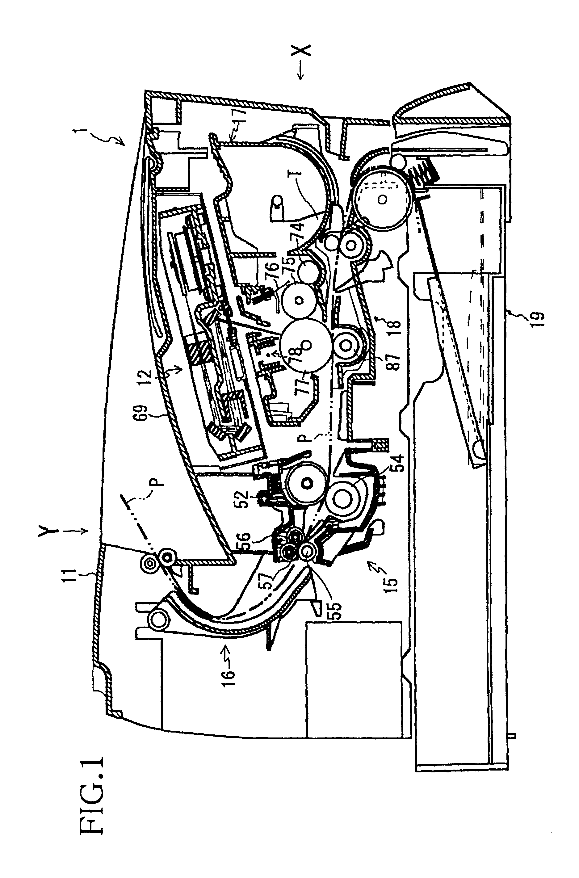
[0032]Referring first to FIG. 1, the basic structure of a laser printer will be described. FIG. 1 is a side cross-sectional view of the laser printer 1 viewed from a direction perpendicular to a sheet feed direction. In FIG. 1, it is understood that a side shown by the arrow X is a front side, a side shown by the arrow Y is a top side, and a side facing the reader is a left side (when viewed from the front in the direction of arrow X).

[0033]The overall shape of the laser printer 1, defined by the main frame 11, is generally rectangular. At the bottom of the main frame 11, a sheet feeder 19 is provided so as to store and feed sheets P. A sheet P is fed from the sheet feeder 19 to a transport unit 18 via a front portion of the laser printer 1. Disposed a...

second embodiment

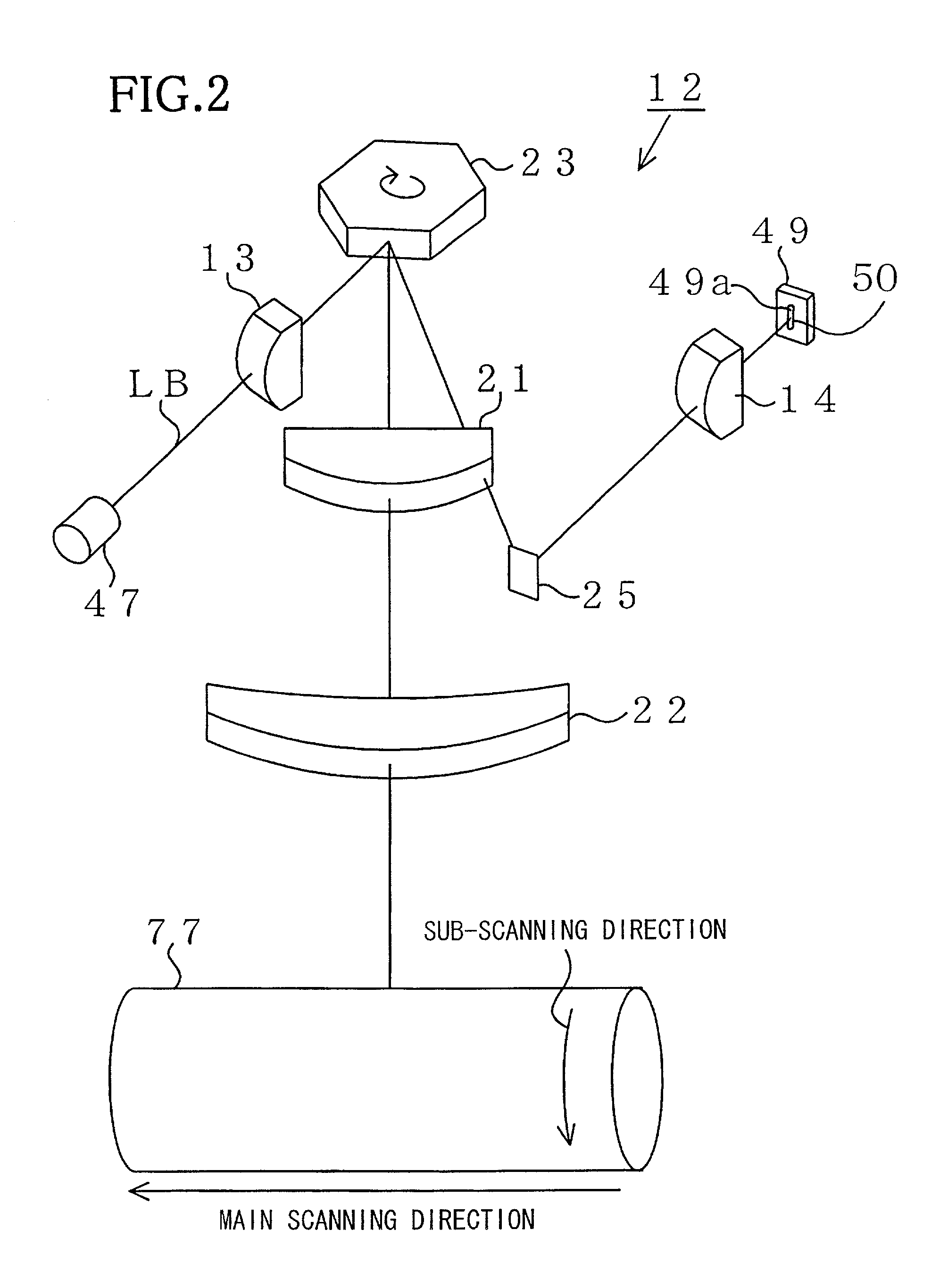
[0055]Referring now to FIGS. 5A through 5C and 6, a laser beam scanner according to the invention will be described.

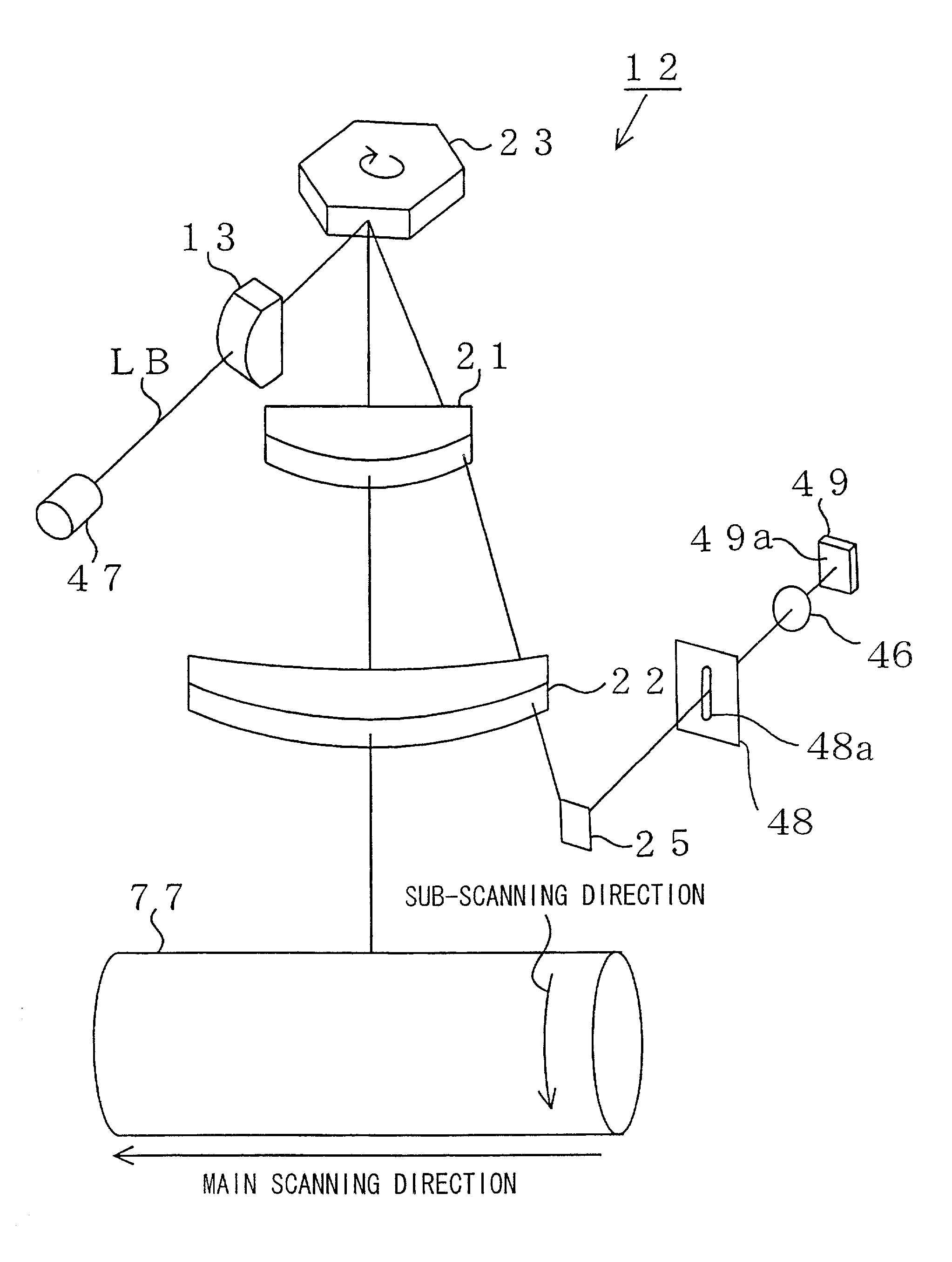
[0056]FIG. 5A is a schematic diagram showing a BD optical path sectioned along the sub-scanning direction. FIG. 5B illustrates the relationship between beam spots passing through a slit and a light-receiving surface 49a of a beam detector 49. FIG. 5C illustrates the relationship between beam spots incident upon the beam detector 49 and the light-receiving surface 49a of the beam detector 49. The structure of the laser beam scanner of the second embodiment is the same as that of the first embodiment except for the BD optical path.

[0057]As shown in FIGS. 5A, 5B, 5C and 6, a member 48 formed with a slit 48a (FIG. 5B) is placed before the beam detector 49, and a converging lens 46 is placed between the member 48 and the beam detector 49. A laser beam LB reflected by a polygon mirror 23 is focused into the slit 48a in the BD optical path. Then the laser beam LB passing thro...


PUM


Abstract

In a laser beam scanner according to the invention, L2/L1>L4/L3 is satisfied, where L2/L1 is the lateral magnification in the sub-scanning direction in an optical path from a polygon mirror to a photosensitive drum, and L4/L3 is the lateral magnification in the sub-scanning direction in an optical path from the polygon mirror to a beam detector. Accordingly, the light-receiving width of the beam detector can be reduced as compared with a conventional laser beam scanner where L2/L1=L4/L3.

Description

BACKGROUND OF THE INVENTION[0001]1. Field of Invention[0002]The invention relates to a laser beam scanner that scans a laser beam across a photosensitive member to form an image thereon.[0003]2. Description of Related Art[0004]Such a laser beam scanner 100, as shown in FIG. 7, has conventionally been known. FIG. 7 illustrates the basic structure of the conventional laser beam scanner 100.[0005]The laser beam scanner 100 includes a laser light source 101 into which a semiconductor laser element and a collimator lens are integrated, a cylindrical lens 102 that converges the laser beam emitted from the laser light source 101, a polygon mirror 103 that deflects the laser beam having passed through the cylindrical lens 102, a first fθ lens 104 and a second fθ lens 105 that converge the laser beam deflected by the polygon mirror 103 on a photosensitive drum 110, a beam detector 106, as a light-sensing element, that detects the laser beam having passed through the second fθ lens 105, and a...

Claims


Application Information

Patent Timeline
IPC IPC(8): B41J27/00H04N1/047H04N1/113
CPCH04N1/113H04N1/047
Inventor KATO, RYOTA
Owner BROTHER KOGYO KK
Why Eureka
Try Eureka