Ultrathin high-gain narrow beam antenna and anti-theft carpet

A narrow-beam antenna and high-gain technology, which is applied in the field of ultra-thin high-gain narrow-beam antenna and anti-theft carpet, can solve the problems of inconvenient use in special application scenarios, unsatisfactory effect, and small gain, and achieve excellent anti-theft performance and compact structure , the effect of reducing the beam width

Pending Publication Date: 2019-10-25
无锡凯施智联软件科技有限公司
View PDF0 Cites 3 Cited by
  • Summary
  • Abstract
  • Description
  • Claims
  • Application Information

AI Technical Summary

Problems solved by technology

Most of the current narrow-beam antennas have the disadvantages of large size and small gain, which are not convenient for some special application scenarios, or the effect is not ideal

Method used


Image

  • Ultrathin high-gain narrow beam antenna and anti-theft carpet
  • Ultrathin high-gain narrow beam antenna and anti-theft carpet
  • Ultrathin high-gain narrow beam antenna and anti-theft carpet

Examples


Embodiment 1

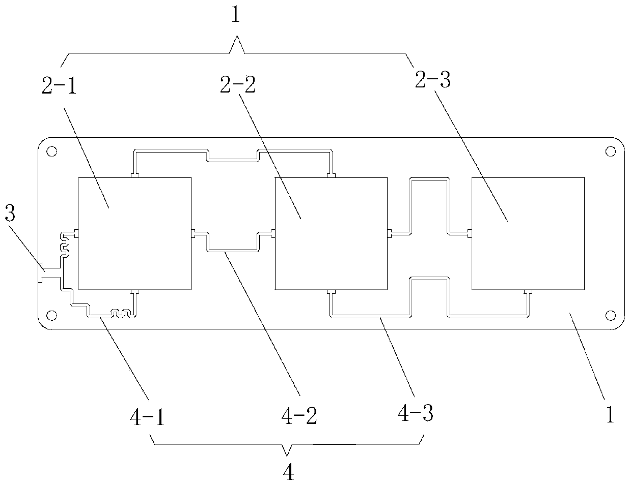
[0034] Such as figure 1 As shown, an ultra-thin high-gain narrow-beam antenna includes: a vibrator reflector 1, an antenna vibrator 2 and a feed network are arranged on the vibrator reflector 1; it is characterized in that the antenna vibrator 2 includes sequentially spaced The first vibrator 2-1, the second vibrator 2-2, and the third vibrator 2-3 arranged on the same surface of the vibrator reflector 1, each of the antenna vibrators 2 is a square metal plate, and the square The side length of the metal plate is 0.25λ, where λ represents the central wavelength of the antenna.

[0035] Wherein, the vibrator reflector 1 is made of double-layer copper plates, and a multi-layer high-density FR-4 glass fiber board is arranged between the two layers of copper plates; the dielectric constant of the vibrator reflector 1 is between 2.5 and 2.8 Between; the thickness of the vibrator reflecting plate 1 is not more than 3.5mm.

[0036] Each antenna element 2 and feed network are etched...

Embodiment 2

[0041] Such as Figure 4 , Figure 5 As shown, an anti-theft carpet includes: a carpet body 5, a detection antenna 6 embedded in the carpet body 5, and the detection antenna 6 is as described in the first embodiment.

[0042] Wherein, the carpet body 5 includes: a hard rubber bottom plate 5-1 and a carpet covering layer 5-2 covered on the hard rubber bottom plate 5-1, and the detection antenna 6 is embedded in the hard rubber bottom plate 5 . In this embodiment, preferably, a groove 5-3 for accommodating the detection antenna 6 is provided on the hard rubber bottom plate 5-1, and a cover plate 5-4 is provided corresponding to the groove 5-3. The cover The plate 5-4 covers the upper surface of the detection antenna 6 to prevent the detection antenna 6 from being damaged due to trampling.

[0043] Preferably, the carpet body 5 is rectangular, and a plurality of detection antennas 6 lined up are embedded in the carpet body 5, and each detection antenna 6 is along the long side...


PUM


Abstract

The invention discloses an ultrathin high-gain narrow beam antenna. The ultrathin high-gain narrow beam antenna comprises an oscillator reflection plate, and an antenna oscillator and a feed network which are arranged on the oscillator reflection plate. The antenna oscillator comprises a first oscillator, a second oscillator and a third oscillator which are sequentially arranged on the same surface of the oscillator reflection plate at intervals, wherein each antenna oscillator is a square metal plate, the side length of the square metal plate is 0.25[lambda], and [lambda] represents the central wavelength of the antenna. According to the invention, the three antenna oscillators 2 with the side length of 0.25[lambda] are arranged on the same surface of the oscillator reflection plate at intervals, so that the structure is compact, and the thin and small antenna is favorably achieved. The beam width is reduced and the gain is increased by combining a specific oscillator reflection plateand a feed network through array combination. Through experimental simulation, the gain of the ultrathin high-gain narrow beam antenna provided by the present embodiment is above 9dBi, and the 3dB width is less than 45 degrees. The invention also discloses an anti-theft carpet.

Description

technical field [0001] The invention relates to the technical field of antennas, in particular to an ultra-thin high-gain narrow-beam antenna and an anti-theft carpet. Background technique [0002] Radio frequency identification is a non-contact automatic identification technology. In an RFID (Radio Frequency Identification, radio frequency identification) system, identification information is stored in an electronic data carrier, and the electronic data carrier becomes a transponder. The identification information stored in the transponder is read by the reader. In some applications, the reader can not only read the stored information, but also write data to the transponder. This read and write operation is through wireless communication between the two parties. to achieve. Microstrip antenna, as a commonly used directional antenna form in RFID system, is of great significance to the development and application of RFID. [0003] In recent years, with the continuous expan...

Claims


Application Information

Patent Timeline
Patent Type & Authority Applications(China)
IPC IPC(8): H01Q1/22H01Q1/36H01Q1/38H01Q1/40H01Q1/50H01Q9/06H01Q15/24H01Q19/10H01Q21/00H01Q21/08A47G27/02
CPCA47G27/02H01Q1/2225H01Q1/36H01Q1/38H01Q1/40H01Q1/50H01Q9/06H01Q15/24H01Q19/10H01Q21/0006H01Q21/0075H01Q21/08
Inventor 管睿王俊峰
Owner 无锡凯施智联软件科技有限公司
Why Eureka
Try Eureka